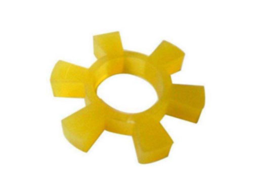
 T type plum blossom hexagonal water pump counter wheel padT-shaped plum blossom hexagonal water pump for wheel pad products...
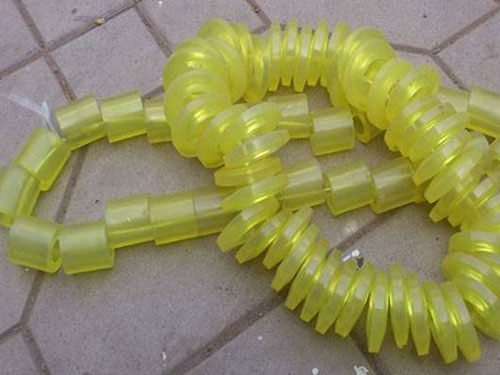 Elastic sleeveThe elastic sleeve uses a number of non-metal elastic...
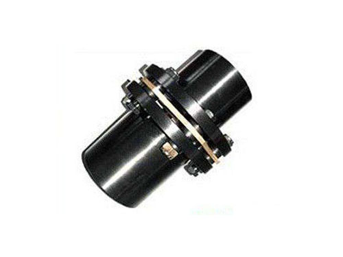 JMⅡ type non-counterbore basic diaphragm couplingJMⅡ type non-counterbore basic diaphragm coupling...
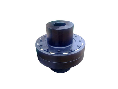 HL nylon rod pin couplingHL nylon rod pin coupling has good toughness...
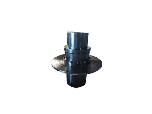 WGP type drum gear coupling with brake discThe gear coupling is made of the same number of teeth...
The size analysis of the coupling diaphragm and the maintenance method of the drum-shaped gear coupling
Size analysis of coupling diaphragm:
120. In order to facilitate the installation, it is better to put the two half couplings in the 150-3 incubator or oil tank for preheating, so that the inner hole size increases and it is easy to install.After installation, make sure that the shaft head cannot protrude from the end face of the half coupling, and it is better to be flush.Detect the distance between the two halves of the coupling: take the average of the readings of 4 to 0 points measured along the two inner sides of the flange of the half coupling, and the sum of the measured dimensions of the extension and the two diaphragm sets, two The error is controlled within the range of 0.4-XNUMXmm.
10. Before installation, check whether the two shafts of the prime mover and the working machine are concentric, whether there are wrapping paper and scratches on the surfaces of the two shafts, whether there are debris in the inner holes of the two half couplings of the coupling, and whether there is any edge of the inner hole If there are bruises, the shaft and half coupling should be cleaned up, and the bruises should be treated with a fine file.Then check whether the inner hole diameter and length of the two half couplings are consistent with the diameter and shaft elongation of the prime mover and working machine.In general selection, it is better to make the length of the prime mover and the working machine end half coupling less than 30-XNUMXmm of shaft elongation.
Diaphragm coupling current collector equipment is at the non-load end of the motor shaft, and it only relies on the single-end bearing of the motor to form a cantilever structure.The unbalanced torque of the motor during start-up and operation will easily cause radial vibration of the collector equipment, which may cause uneven brush wear and shorten the service life of the brush; in the worst case, the collector ring and the brush will ignite due to poor contact. , Ablate the surface of the collector ring, or even damage the collector's diaphragm coupling. In the normal condition of the sensor equipment, the selected coupling is a rigid connection, which is a big sensation, and when the concentricity is small and 0.2mm is larger than 0.05mm, it is recommended Use flexible connections.Rigid connection can be used outside this scale.
When the torque sensor is in use, its equipment should be placed between the power source and load of the two sets of couplings. The power load and load equipment should be fixed to prevent sensation, otherwise it will cause the appearance to fail to work properly.Another point is that when standardizing the application of torque appearance, regardless of the method and equipment selected, the coupling must accept the corresponding axial force and bending moment, and try to prevent the appearance of excessive force, which directly causes the appearance of damage and cannot be used.When using a torque sensor, pay attention to the question of the equipment, because the torque sensor belongs to the power equipment, especially the application of the dynamic torque sensor connected to the motor. The measurement of large torque force needs to be used with caution, load equipment and couplings, couplings The connection between the sensor and the sensor and the connection between the coupling and the power equipment must not be neglected.
The drum gear coupling is one of the basic parts of the machinery industry. It is mostly used in the transmission of heavy loads, high speed requirements, and large adjustment errors and deviation angles of the two coupling shafts.The gear teeth of its external gear sleeve are arc-shaped along the length direction, while the gear teeth are in a drum shape when viewed from the top of the tooth, that is, on the same tangent plane parallel to the axis, the tooth thickness gradually changes from the middle of the tooth length to the two ends. The tooth profile of the inner ring gear meshing with the outer gear sleeve is linear.Because the tooth top surface and tooth flank of this kind of external gear sleeve are both arc-shaped (which is different from the characteristics of ordinary gear couplings), the entire coupling becomes a double joint and is flexible.Due to its structure, the drum gear coupling has the following characteristics: ① It can compensate the deviation of angular installation and radial installation due to the non-coincidence of the two coupling axes, and it can be driven in the horizontal direction or Under the special structure, vertical transmission, ②compact structure, low weight and moment of inertia, ③because all parts are circular, so the unbalanced moment is small.
Maintenance method of drum gear coupling:
200. If you need to remove the gear ring, use tools and don't knock it to avoid bending or damage to the shaft.When reinstalling, heat the ring gear to about 0.01°C before installing it on the shaft.The interference between the outer gear ring and the shaft is generally 0.03~XNUMXmm.
XNUMX. The indirect tube or other parts in the reassembly should be assembled according to the original markings and data.
XNUMX. Tighten the bolts evenly with a torque wrench.
50. Check the tooth surface meshing of the drum-shaped gear coupling. The contact area along the tooth height is not less than 70%, and the tooth width is not less than XNUMX%. The tooth surface must be free from severe corrosion, abrasion and cracks.
0.03. The full circle runout of the outer gear ring of the drum gear coupling is not more than 0.02mm, and the end circle runout is not more than XNUMXmm.
The performance of the drum gear coupling requires it to have the ability to compensate the relative displacement of the two shafts, and the angular displacement of the two horizontal axis transmission shafts is ultimately reflected in a pair of meshing teeth. The allowable deflection angle depends on The size of the backlash between the meshing teeth.The choice of backlash is more critical.Considering that the gear coupling is different from the gear transmission, in terms of structure, a pair of internal and external gears are assembled together and rotate together at the same circumferential speed.There are different technical solutions for the development of drum-shaped gear couplings. The design method for calculating the tooth thickness of the TGII drum-shaped gear coupling according to the thickness of the internal and external teeth indexing circle has the following characteristics:
0.02. Interchangeability of couplings.Interchangeability requirements are a difficult point in the development of drum gear couplings.Generally, the couplings produced by many domestic factories are not interchangeable.At present, most of the drum gear couplings have the twisted bolt holes of the two halves of the inner gear ring using the method of drilling and reaming, and then marking and checking into the seat for assembly.Couplings manufactured in this way are not interchangeable.According to the needs of the market, especially the special requirements of the metallurgical industry, in the design of the TGII drum gear coupling, the position tolerance of the two halves of the inner gear ring connected to the stranded bolt hole relative to the centering circle is φXNUMX. One requirement is on the machining and CNC lock bed.In this way, the requirement of interchangeability not only reduces the labor intensity of workers' maintenance and replacement of spare parts, but also shortens the online maintenance time, which has obvious economic benefits.
XNUMX. The meshing accuracy is good.The manufacturing of drum gears is generally made on the hobbing machine to make the hob track according to the displacement radius required by the design and process it with a profiling template. Almost all domestic manufacturers use this method.When using template profiling, the key to the technology lies in the influence of non-linear factors such as inertia, friction damping, drive screw gap, and elastic deformation caused by insufficient rigidity of the transmission chain when the tooth is milled to the middle of the tooth profile. Generally, it is difficult to process the correct arc surface of the drum tooth, and it is often necessary to have a skilled worker to master it based on his work experience. TGII drum-shaped gear coupling, the arc surface of the drum-shaped tooth is formed by numerical control, which is more accurate than the drum-shaped tooth formed by general profiling.
XNUMX. Centering method.There are four centering methods for gear couplings, namely outer diameter centering (two types), tooth side centering, and web centering.There are two types of outer diameter centering, namely, the part of the external tooth tip circle matches the internal tooth root circle and the external tooth tip circle matches the internal tooth root circle.