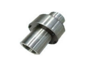
 ZL type elastic pin gear couplingZL type elastic pin gear coupling is the use of...
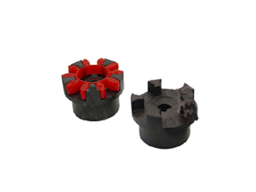 XL type star elastic couplingXL type star elastic coupling and other coupling...
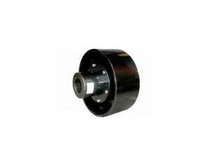 HLL type brake wheel elastic pin couplingHLL type brake wheel elastic pin coupling has...
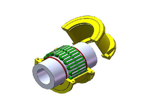 JS type housing radial mounting type couplingSelection of JS type housing radial mounting type coupling...
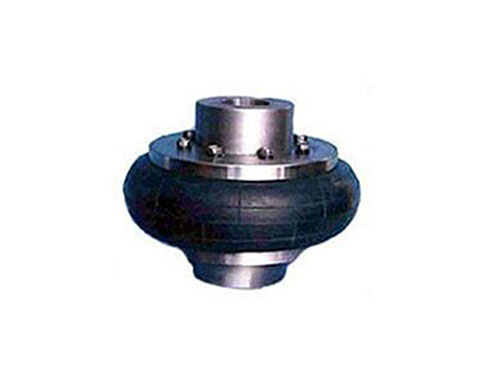 Tire coupling for LLB metallurgical equipmentTire coupling for LLB metallurgical equipment belongs to...
Alignment method and installation points of elastic coupling
Alignment method of elastic coupling:
XNUMX. Fix the outer foot on one side of the motor of the lifting accessories coupling, and move the inner foot until the eccentric line between the motor and the pump center is zero.In order to ensure that the motor does not move arbitrarily, after fixing the feet of one side of the motor, the other side should be supported by the top wire.
XNUMX. Fix the inner feet of the coupling and move the outer feet to make the eccentricity of the two center lines zero.
There are two categories of flexible couplings:
XNUMX. Spiral groove type: The spiral groove type elastic coupling has a continuous multi-turn long slot. This type of coupling has particularly excellent elasticity and small bearing load.It can withstand various deviations and is more suitable for correcting deflection angle and axial deviation, but its ability to deal with eccentricity is relatively poor. Because the spiral groove needs to be bent in two different directions at the same time, a large internal pressure will be generated, thus Lead to premature damage to the coupling.Although the long spiral groove coupling can easily bend under various deviations, it has the same effect on the rigidity of the coupling under the torsional load.Excessive swing clearance under torsional load will affect the accuracy of the coupling and weaken its overall performance.The spiral groove type elastic coupling is a more economical choice, suitable for low torque applications, especially in the connection of encoders and other lighter instruments.
3. Parallel groove type: Parallel groove type elastic coupling usually has 5-XNUMX slots to cope with the problem of low torque rigidity.Parallel grooves take into account that the cut grooves can be shortened without reducing the ability to withstand deviations. The short cut grooves can increase the torque rigidity of the coupling and overlap, so that it can withstand considerable torque.This performance makes it suitable for light load applications.For example, the connection of a servo motor and a ball screw.However, this kind of performance will increase the bearing load as the slot size increases, but in most cases, it can adequately protect the bearing.Increasing size means increasing the ability to withstand eccentricity.
Most of the flexible couplings are made of aluminum alloy, and some manufacturers also provide flexible couplings made of stainless steel.In addition to the stainless steel elastic coupling, it also increases the torque bearing capacity and rigidity, and can even reach twice that of similar products made of aluminum alloy.However, this increased torque and rigidity will be offset by increased mass and inertia to a corresponding extent.Sometimes the backside influence will outweigh its advantages, so users have to look for other types of couplings.After the elastic diaphragm of the diaphragm coupling of the main reducer of the central transmission tube mill is broken, it is necessary to observe and analyze the scene in detail to find out the failure situation and keep the required inspection records.Jaeger contacted the manufacturer, signed an ordering contract for parts, analyzed the cause of the failure carefully and carefully, and worked out a practical and feasible solution based on the actual situation.The main points of the measures to deal with the fracture of the elastic diaphragm are: record in detail the installation position and sequence of the connecting bolts and other accessories; after the diaphragm coupling is disassembled, use the bracket to support the transmission shaft, keep it in a horizontal state, and prevent the elastic diaphragm and the connecting ring from being damaged. Force deformation; take reasonable measures to connect the wind deflector and the transmission pipe, remove the gaps, and prevent the wind carrying a large amount of dust and water vapor from entering the cavity between the wind deflector and the elastic diaphragm and corroding the elastic diaphragm; measurement and calibration For the center line of the tube mill and the main reducer, when the tube mill is running normally, try to make the transmission connection center of the tube mill and the output shaft of the reducer lie on the same straight line, and make the end face of the transmission connection flange on the vertical plane; Hinge the connecting bolt holes and bolts of the elastic diaphragm and the drive shaft; correct the concentricity of the elastic diaphragm with the transmission tube of the tube mill and the output shaft of the reducer; adjust the thickness of the adjustment gasket reasonably to avoid the elastic diaphragm from bearing the axial force .In short, after the elastic diaphragm is broken, the cause of the failure must be found at first. Taking into account the reasons of equipment, tools, experience and technology, try to ask the manufacturer to send or come to guide the maintenance to determine the quality, save time, and reduce loss.
Introduce the correct choice of diaphragm coupling:
XNUMX. Diaphragm couplings are often used in servo systems. Diaphragms have good torque rigidity, but are slightly inferior to bellows couplings.
XNUMX. Diaphragm coupling is very delicate, it is easy to be damaged if it is misused or not installed correctly in use.Therefore, it is very important that the deviation is within the tolerance range of the normal operation of the coupling.
XNUMX. The diaphragm coupling is composed of at least one diaphragm and two shaft sleeves.The diaphragm is fastened to the sleeve with a pin and generally will not loosen or cause backlash between the diaphragm and the sleeve.Some manufacturers provide two diaphragms, and some provide three diaphragms, with one or two rigid elements in the middle, and the two sides are connected to the shaft sleeve.
Fourth, the characteristic of diaphragm coupling is a bit like a bellows coupling. In fact, the way the coupling transmits torque is similar.The diaphragm itself is very thin, so it is easy to bend when the relative displacement load is generated, so it can withstand up to 1.5 degrees of deviation, while generating a lower bearing load in the servo system.
The structure of the diaphragm coupling is that the diaphragm group is fixed to the two halves of the coupling with bolts. The bolt holes are divided into 4 holes, 6 holes, 8 holes, 10 holes, and 12 holes.The form of the diaphragm is divided into continuous polygonal ring, circular ring, separated connecting rod shape, spoke shape, formed diaphragm and waved diaphragm.The characteristics of continuous polygonal ring and circular ring: each finished coupling should be composed of several diaphragms of equal thickness. The outer edge of each piece is arc-shaped, which has good elasticity, simple shape, convenient processing, but poor elasticity. In addition, The elasticity with a small number of edges is better than that with a large number of edges, but if the number of edges is too small, the stability will also be reduced. When one-way operation is performed, only half of the ring edges carry the transfer torque.
Eight points for installing diaphragm couplings:
XNUMX. The allowable axis deviation of the coupling includes radial, angular and axial deviations.When installing, please adjust the axis deviation within the allowable value range of the corresponding product catalog.
XNUMX. If there is an abnormal sound during operation, please stop the operation immediately and check the installation accuracy and screw loosening.It is recommended to apply adhesive on the outer surface of the screw after installation and debugging to increase the protection performance.
XNUMX. When multiple deviations occur at the same time, the corresponding allowable value should be halved.
1. In order to prolong the service life of the coupling, it is recommended to set the axis deviation within 3/XNUMX of the allowable value.
XNUMX. Products with diaphragms have edges and may cause injuries. It is recommended to wear thick gloves when installing.
XNUMX. Please install a protective cover and other devices around the coupling for stability.
XNUMX. Tighten the screws after inserting the mounting shaft, otherwise the coupling will be deformed.When tightening the screws, please use a torque wrench, do not use screws other than the accessories for installation.
XNUMX. When the shaft center deviation exceeds the allowable value during installation, the coupling may be deformed, resulting in damage or shortened service life.