 GY, GYS, GYH type rigid couplingThe surface roughness of the coupling means adding...
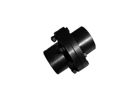
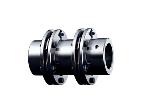 JMⅡJ Type Intermediate Shaft Type Diaphragm CouplingJMⅡJ Type Intermediate Shaft Type Diaphragm Coupling...
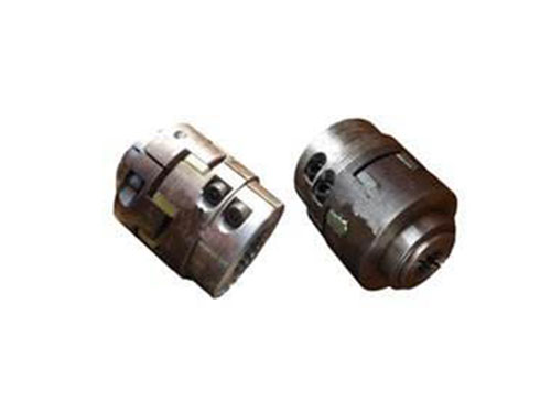 Clamping spline plum blossom elastic couplingClamping spline plum blossom elastic coupling...
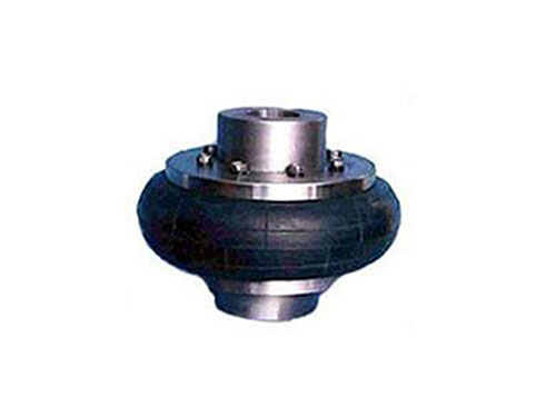 Tire coupling for LLB metallurgical equipmentTire coupling for LLB metallurgical equipment belongs to...
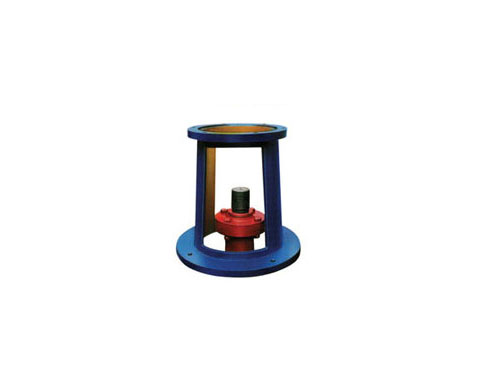 JAI large flange frame <69 standard>, JAII <69 standard> frameThe JAI large flange frame itself has no shaft support...
Alignment plan of pump coupling and inspection items of coupling
The 4-point alignment scheme for pump couplings:
1. Observe the reading of the axial dial gauge first, tap the front and back feet of the movable end with a copper rod, and adjust the axial reading at 3 o'clock to half of the original.Observe the reading of the radial dial gauge, tap the middle of the movable end with a copper rod, and adjust the radial reading at 3 o'clock to half of the original.This requires repeated adjustments.The adjustment result should make the sum within the allowable error range.
2. The projection of the circle of the movable end face of the motor on the end face of the fixed end is approximately regarded as a perfect circle, because the distance from the center of the movable end to the end face of the fixed end does not change.If you want to achieve it at the same time, the axis of the movable end and the axis of the fixed end are on the same line, which is just an ideal alignment state.
3. In actual alignment, set the allowable error first. When the error generated during alignment is within the allowable error range, alignment ends.In many occasions, the lower detection point of the pump cannot be detected, and the alignment work cannot be performed.
4. Horizontal alignment does not need to calculate the amount of front and rear feet of the movable end, clear the axial and radial dial gauges at 1 o'clock, and read the readings of the axial and radial dial gauges at 3 o'clock, using copper The rod taps the movable end to adjust the axis.
Before the pump coupling device, clean the end faces of the two shafts, and examine the common conditions such as the end face keyway; in the future, the pump coupling device should be operated normally for a shift, and the screws should be examined; in order to avoid fretting wear of the diaphragm during high-speed operation , Cause the diaphragm bolt hole to appear micro-cracking and damage, you can apply a solid smoothing agent such as molybdenum disulfide between the diaphragms or treat the surface of the diaphragm with a wear-reducing coating, a coupling for high-speed pumps; it should be prevented for a long time Overload use and operation disorder occur; in task operation, it is necessary to check whether the pump coupling can produce abnormal scenes, if any abnormal scenes occur, and repair it; when it can be caused by the running pump coupling and equipment disorder Appropriate safety protection measures are adopted in each site of the country.Pay attention to the problem of the pump coupling device, and handle it correctly to confirm the completion of the installation.Regular observation, inspection, and maintenance work to achieve practical installation.
The heat treatment of the pump coupling is the operation technology of the metal or alloy in the solid range, through the organic cooperation of family, heat preservation, and cooling, so that the metal or alloy can change the internal arrangement to obtain the required function. Heat treatment is an indispensable part in the modern machinery industry and metallurgical industry to improve product quality and extend the service life of machine parts.
Coupling inspection is a key link related to installation, use and life. Reasonable inspection in accordance with inspection procedures will help to provide work speed to avoid missed inspections and false inspections during production.Generally speaking, the inspection items of the coupling mainly include the following items:
XNUMX. Check the dimensional accuracy of the coupling
When checking the dimensional accuracy of the coupling, check the drawings, process and technical conditions.Generally, check the shape dimensions first, such as the shape, hole, shaft diameter, and then check the positioning dimensions, such as margins, center distances, etc.When inspecting parts with complex shapes and various sizes, a table should be drawn before the inspection, and the shape size should be listed in the table first, and then the positioning size should be listed in the table, and then measure according to the order of the table, and write the measurement results In the actual measured size column, so that the size will not be missed, and the inspection quality can be confirmed.
XNUMX. Inspect whether the materials used are up to standard
When inspecting parts, first check the specifications and grades of the materials used in the parts with reference to the title bar of the drawing and the process documents, and check the grain direction and status of the plates.Couplings are also called couplings.A mechanical component used to connect the driving shaft and the driven shaft in different mechanisms to rotate together and transmit motion and torque.Sometimes it is also used to connect shafts and other parts (such as gears, pulleys, etc.).Dimensional inspection will be carried out after passing the test.
XNUMX. Measuring the form and position error
When measuring form and position errors, pay attention to the measurement datum, and pay attention to the elements marked with the principle of tolerance and the principle of large entity.The diaphragm coupling is connected with the two halves of the coupling in a staggered manner with bolts. Each group of diaphragms is made up of several pieces. The diaphragms are divided into connecting rod type and whole piece type of different shapes.The diaphragm coupling relies on the elastic deformation of the diaphragm to compensate for the relative displacement of the connected two shafts.Drum-shaped gear coupling shell mold molding simplifies the processing technology, low cost, the larger the tooth width, the larger the drum radius, the larger the backlash required, and it is commonly used in various hydraulic pumps, lubrication pumps, and pneumatics. Pumps, compressors, textile machines and other machinery.For the elements that are not marked with geometric tolerances on the paper, the inspectors can find the tolerance values and measure them according to the national or enterprise standards as needed.Such as the coaxiality, circular runout of the coupling, the symmetry of the keyway, the position of the hole and so on.
Fourth, check the shape, surface roughness and surface quality of several couplings
Compare the front view and other views to check whether the geometry of the coupling is qualified; check whether the position of each element is correct, such as holes, grooves, etc.; check surface roughness, surface quality, such as scratches, bumps, deformation, cracks, etc.