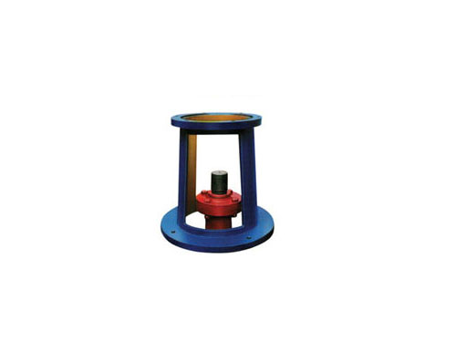
 JAI large flange frame <69 standard>, JAII <69 standard> frameThe JAI large flange frame itself has no shaft support...
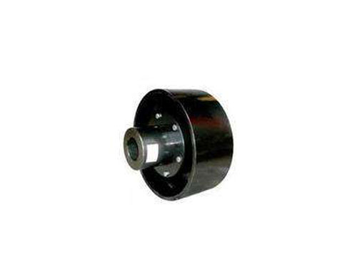 LTZ elastic sleeve pin coupling with brake wheelLTZ (formerly TLL type) with brake wheel elastic sleeve pin...
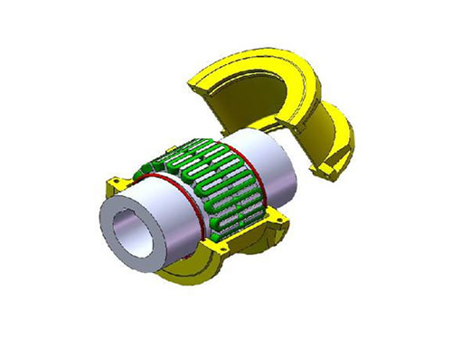 JS type housing radial mounting type couplingSelection of JS type housing radial mounting type coupling...
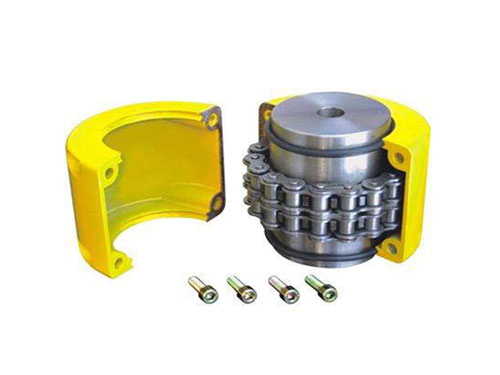 Roller chain couplingRoller chain couplings can be used in textiles, agriculture...
 WGT type gear coupling with intermediate sleeveWGT type connecting middle sleeve gear coupling is working...
Diaphragm stress analysis and the form of GⅡCLZ drum gear coupling
The diaphragm group is the main elastic element of the diaphragm coupling.During operation, the diaphragm group is subjected to complex forces such as stretching, squeezing, and shearing, and is in a complex state of force, and thus transmits torque and motion, while absorbing vibration and compensating for deviation.
Since the stiffness of other parts in the coupling is much greater than that of the diaphragm, and the force of the diaphragm is more complicated, only the stress analysis of the diaphragm is discussed here.In order to simplify the calculation, the surface shear force generated by the small relative movement between the diaphragms is not considered, that is, all the diaphragms are regarded as a whole.The load borne by the diaphragm is as follows:
XNUMX. Forced displacement of the diaphragm group
Although the torque transmitted by the diaphragm assembly is very large when the diaphragm coupling is working, practice has proved that the main failure of the diaphragm coupling is not caused by the insufficient torque transmission capacity of the diaphragm assembly, but the alternating change of the diaphragm. Caused by cyclic compound stress.This composite stress is mostly caused by the additional load caused by the misalignment of the two shafts connected by the diaphragm coupling.
Second, the axial offset of the diaphragm coupling
The axial offset K of the diaphragm coupling is affected by the size of the coupling and the number of bolts. The larger the size of the coupling, the greater the axial offset that it can withstand.Axial deviation will cause great stress on the diaphragm. Therefore, in order to determine the long-term service life of the coupling, it is required that the diaphragms are as close as possible during installation and the diaphragms are as flat as possible.At the same time, the axial deviation of the equipment caused by thermal expansion and contraction needs to be taken into account.For the double diaphragm coupling, after the axial deviation of the coupling is averaged by the diaphragm groups on both sides of the intermediate body, the axial deviation of the diaphragm group is half of the axial deviation of the diaphragm coupling.
XNUMX. Angular deviation of the diaphragm coupling
The installation error of the axial angle causes the diaphragm to undergo periodic bending and deformation along the axial direction, which is the main factor that determines the fatigue life of the diaphragm.The diaphragm coupling has an angular deviation, and a large angular deviation will cause the diaphragm assembly to bear a large additional bending moment.For double diaphragm couplings, the angular deviation of the diaphragm group is half of the angular deviation of the coupling.
Fourth, the torque borne by the diaphragm
When the diaphragm coupling transmits torque, the torque is driven by the driven bolt by the diaphragm element through the active bolt, and the tension in the diaphragm along the tangential direction of the bolt distribution circle generated by the torque.Torque causes the tensile or compressive stress generated by the diaphragm to vary with the operating conditions, but under some operating conditions, it can be regarded as a constant stress.
Five, the centrifugal stress borne by the diaphragm
Diaphragm couplings are usually installed on high-speed transmission shafts. The centrifugal inertia force of high-speed machinery is important in structural stress calculations.The direction of the centrifugal inertia force generated by the mass of bolts, washers, etc. and the centrifugal inertia force generated by the mass of the diaphragm group itself are both radially outward, so that the diaphragm group is subjected to centrifugal tensile stress.The centrifugal stress that the diaphragm bears varies greatly with the speed, but under some operating conditions, it can also be regarded as a constant stress.
GⅡCLZ drum gear coupling is one of the removable rigid couplings.It uses internal and external tooth meshing to realize the torque and rotation transmission between the two halves of the coupling. It is suitable for connecting two concentric shafts and has the performance of specifically compensating the relative displacement of the two shafts.It is composed of main parts such as inner gear ring, gear shaft sleeve and end cover. Generally, the small size GⅡCLZ drum gear coupling end cover and inner gear ring can be integrated.
There are hundreds of varieties of GⅡCLZ drum-shaped gear couplings, but there are two basic forms: 1. Combination of internal and external teeth; 2. Combination of end-tooth.Other forms are deformations on these two foundations.The gear clutch with internal and external gears has a large transmission torque ratio. The design takes into account the different needs of users and is deliberately designed so that the lengths of the shaft ends on both sides of the teeth are not consistent, so that users can choose the installation direction according to their needs.Therefore, there is no stipulation on which end faces where.
Pay attention to when installing:
If it is the original equipment to be replaced, it should generally be the same as the original direction. If it is a newly designed and manufactured equipment, it should not interfere with other surrounding parts. The more the inner and outer tooth joint surfaces, the more The principle of installation.
The maintenance of GⅡCLZ drum gear coupling is generally carried out according to the following methods:
0.03. The full circle runout of the outer gear ring of the coupling is not more than 0.02mm, and the end circle runout is not more than XNUMXmm.
200. If you need to remove the gear ring, you must use tools and don't knock, so as to avoid bending or damage to the shaft.When reinstalling, heat the ring gear to about 0.01°C before installing it on the shaft.The interference between the outer gear ring and the shaft is generally 0.03~XNUMXmm.
XNUMX. The indirect tube or other parts in the reassembly should be assembled according to the original markings and data.
XNUMX. Tighten the bolts evenly with a torque wrench.
50. Check the gear tooth surface meshing condition of the coupling. The contact area is not less than 70% along the tooth height and not less than XNUMX% along the tooth width. The tooth surface must not have serious corrosion, abrasion and cracks.