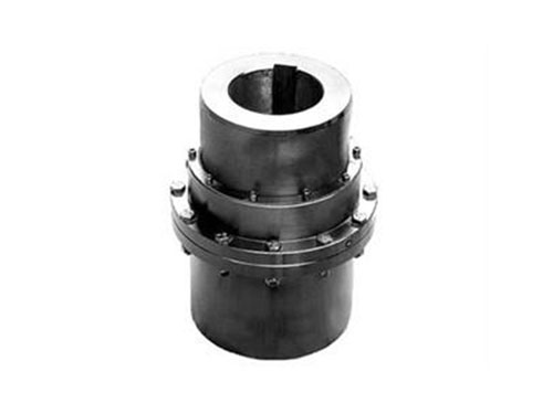
 GICL type-drum gear couplingGICL type-drum gear coupling (JB/T 88...
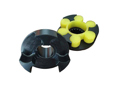 LMZ-ⅡPlum-shaped elastic coupling with brake wheelLMZ-Ⅱ (formerly MLL-Ⅱ) type with brake wheel plum...
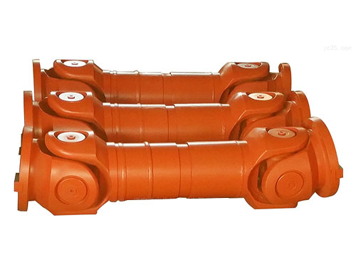 SWP-E type cross shaft universal couplingSWP-E type cross shaft universal coupling is used to...
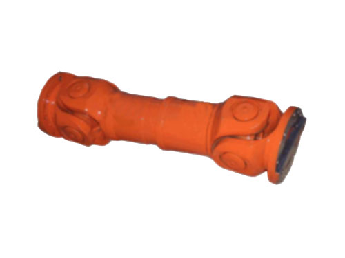 WF type non-telescopic flange universal couplingUniversal coupling is a kind of coupling,...
 YLD type flange couplingYL type flange coupling can be made of gray cast iron or carbon...
The technical requirements of plum coupling and the working process of diaphragm coupling
The plum blossom coupling has a good balance performance and is suitable for high-speed applications (the speed can reach 30000 rpm), but it cannot handle large deviations, which are axial deviations.Large eccentricity and deflection angle will produce a larger bearing load than other servo couplings.Another value of concern is the failure of the plum blossom coupling.Once the quincunx elastic spacer is damaged or fails, the torque transmission will not be interrupted, and the metal claws of the two shaft sleeves mesh together to continue to transmit the torque, which is likely to cause problems in the system.
The zero-backlash claw type plum blossom coupling evolved on the basis of the straight claw type, but the difference is that its design can be adapted to the application of the servo system, and is often used to connect servo motors, stepping motors and ball screws.The curved surface is to reduce the deformation of the elastic plum spacer and limit the influence of centripetal force on it during operation.The zero-clearance claw coupling is composed of two metal sleeves (usually made of aluminum alloy, stainless steel can also be provided) and a plum blossom elastic spacer.The plum blossom elastic spacer has multiple leaf branches. Like a slider coupling, it also squeezes the plum blossom elastic spacer and the sleeves on both sides to match, and thus its zero clearance performance.Different from the slider coupling, the plum blossom coupling is driven by squeezing while the slider coupling is driven by shear.The disappearance of the preload, resulting in the loss of zero-gap performance, may also be discovered by the user after a serious problem occurs.
Choosing the appropriate plum blossom elastic spacer material according to the actual application is a major advantage of this coupling. It can provide plum blossom spacers of various elastic materials with different hardness and temperature resistance, allowing customers to choose the appropriate material to achieve the actual application. Performance standards.
The plum blossom coupling is a common type of coupling. Many people choose the plum blossom coupling when choosing a coupling. The plum blossom coupling has a simple structure, a small number of parts, a small radial dimension ratio, and no need for lubrication. , The elastic element has a relatively good pressure bearing capacity. Except for the double-flange plum-shaped elastic coupling, we need to move the half coupling axially when replacing the vulnerable plum-shaped elastic coupling, otherwise the replacement will fail. , The position will cause deviation. Although the plum blossom coupling is a small object, it has a big function.
Production technical requirements for plum coupling:
1. The coupling should be cleaned before packaging, and the coupling surface should be coated with anti-rust agent, and the non-coupling surface should be coated with paint or other anti-rust treatment.
2. The coupling needs to be trial-assembled before leaving the factory. The half-coupling and the elastic part should be installed in no less than two positions relative to each other, which should be convenient for assembly and disassembly.
3. The coupling used under working conditions should undergo a balance test with the main shaft system.
4. Large operation compensation refers to the two-axis phase offset formed by comprehensive factors such as manufacturing errors, installation errors, and changes in working load caused by vibration, impact, and temperature changes in the working state.
5. The shape of the elastic part should be smooth and flat, the working surface must not have pitting, and there must be no defects such as impurities, bubbles, cracks, etc. inside.
6. The shaft hole tolerance of the semi-coupling is in accordance with the provisions of GB/T3852-17, and the surface roughness Ra value of the shaft hole is not less than 1.6um.
7. The surface of half coupling, flange coupling, flange half coupling, brake wheel, brake wheel half coupling is not allowed to have cracks, shrinkage holes, air bubbles, slag inclusion and other defects that affect strength. The surface of the brake wheel should be quenched, the hardness is 45~55HRC, and the hardened layer is greater than 3mm.
During the working process of the diaphragm coupling, the coupling may vibrate due to the alternating radial and angular effects. If the rotor is lighter, the vibration of the coupling will become the main vibration source of the rotor system.
1. Adjust the coupling with the meter, find the position and reinstall it, to reduce the impact of coupling machining error and unbalance on the vibration of the fan.
Re-check the alignment of the unit coupling at the test site. The alignment of the unit is in good condition. After reinstalling the coupling, perform a cranking, and perform a meter check on the outer circle of the coupling. It is found that the outer circle is out of tolerance. The coupling has no marking prefix and the installation position cannot be confirmed. Therefore, the coupling is used to connect and then the meter is printed. According to the metering situation, the rotation angle of the intermediate shaft is disassembled and the meter is connected again. Finally, the geometric position is found and then reassembled.
2. Diaphragm distortion caused by changing the bolt installation direction and manufacturing errors.
The diaphragm coupling relies on bolts and diaphragms to transmit torque. The bolt holes under the diaphragm group are equipped with crown bushes and crown washers. The bushes and bolts with pins are matched with a small clearance, and the concentricity and mating surface requirements are high. The concentricity between the half coupling and the intermediate shaft is positioned by the bushing and the pin bolt. If the installation direction is opposite, the thickness of the washer is added, resulting in a shorter positioning surface, poor concentricity, and distortion of the diaphragm assembly.
3. Thicken the diaphragm thickness of the diaphragm group to improve the lateral rigidity of the coupling.
The factors affecting the transverse vibration frequency of the coupling are mainly the mass of the intermediate shaft and the transverse stiffness of the coupling, which are proportional to the stiffness of the diaphragm and inversely proportional to the mass of the intermediate shaft.The quality of the intermediate shaft cannot be changed after processing and shaping, only the stiffness of the coupling, that is, the thickened diaphragm group, can be changed.The diaphragm group is increased from the previous 12mm to XNUMXmm, and the rigidity between the intermediate shaft and the half couplings at both ends is improved.It can be considered that the entire system is a rigid two-degree-of-freedom spring-mass system. By increasing the thickness of the diaphragm group, the influence of the coupling on the vibration frequency of the rotor is reduced.
Next:Nothing