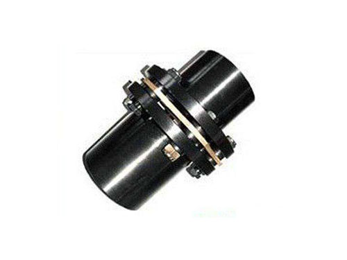
 JMⅡ type non-counterbore basic diaphragm couplingJMⅡ type non-counterbore basic diaphragm coupling...
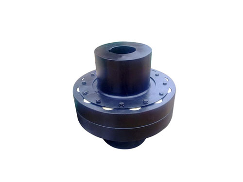 HL nylon rod pin couplingHL nylon rod pin coupling has good toughness...
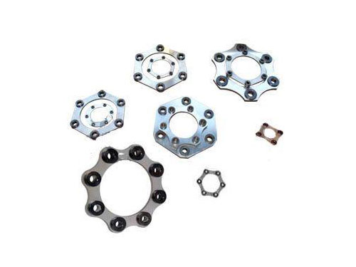 Diaphragm coupling diaphragmDiaphragm couplings have a wide range of applications...
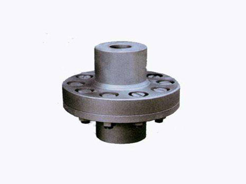 Elastic sleeve pin coupling for pumpElastic sleeve pin coupling for pump: 1. Elastic...
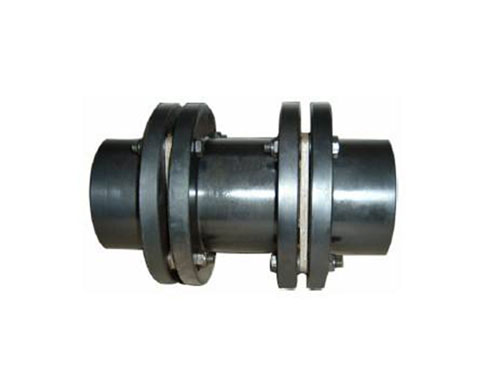 JMJ diaphragm couplingJMJ diaphragm coupling torque control range...
Introduce the method of calculating the torsional stiffness of the diaphragm of the diaphragm coupling
The selection of the diaphragm coupling should be based on the machine type provided by the complete set or the host manufacturer and the shaft power under normal conditions, and should not be over-coded.Of course, other working conditions should be considered in some occasions.When the coupling is required to work normally when the driven machine is overloaded, the type should be selected according to the power of the driving machine; when the driving machine is a motor, the instantaneous short-circuit torque of the motor should be considered if any.Relying on the metal diaphragm to transmit torque and absorb the deformation caused by misalignment, there is no relative movement between parts, no friction and wear, so no lubrication is required, which is in line with the development direction of oil-free process equipment.The gear coupling is a rigid movable coupling. It relies on the relative slippage between the tooth surfaces to compensate for the misalignment of the two shafts. Therefore, the gear coupling should be lubricated, and the lubrication condition determines the gear coupling The key to good or bad work.
Especially in high-speed operation, it is more prominent, such as the separation and leakage of oil under the action of centrifugal force, as well as the selection of lubricating oil, often because the lubrication design uses the bearing lubricating oil of the connected machine instead of the appropriate load capacity Gear lubricants.Therefore, the lubrication problem of high-speed gear couplings is particularly prominent.On the other hand, the wear caused by the relative slippage of the tooth surface will cause a series of problems such as sludge and imbalance.Therefore, although gear couplings were once the choice for high-speed and high-power applications, with the emergence and development of diaphragm couplings, gear couplings have gradually faded out.
Introduce the method of calculating the torsional stiffness of the diaphragm of the diaphragm coupling
1. The membrane segment between two adjacent bolt holes can be equivalent to a cantilever beam, and the method of material mechanics is used to deduce that the connecting rod diaphragm coupling can bear the torque, centrifugal load, axial offset and angular A formula for calculating the internal stress of the diaphragm when it is deflected, and a method for calculating the torsional stiffness of the diaphragm is proposed. It is a typical method to analyze the stress and stiffness of the diaphragm by using empirical formulas, but it is insufficient to consider the stress in the area around the bolt hole The influence of the concentration effect causes a large gap between the calculated stress and the actual stress.
2. A typical study on diaphragm stress and fatigue life using finite element method and thin plate bending theory.The common point is to first analyze the stress of the diaphragm under various single working conditions, and use the combined stress of the three static stresses (axial bending stress, diaphragm stress, and centrifugal stress) as the average stress of the diaphragm, and the rotation angle The stress caused by the offset is regarded as the alternating stress amplitude, and the average stress and the alternating stress amplitude are obtained by static analysis, and then the fatigue analysis is carried out based on this result.
3. When the diaphragm coupling rotates, its angular deviation will produce alternating stress, which alternates once per rotation.The dynamic stress of the diaphragm will cause the fatigue damage of the diaphragm and bolts, so accurate calculation of the dynamic and static composite stress is the key to predicting the life of the diaphragm coupling and determining the work of the diaphragm coupling.
4. The existing related researches are mostly limited to the analysis of the stress distribution of the diaphragm when it is subjected to a certain load, and the dynamic and static composite stress when the diaphragm is actually subjected to a complex load is rarely involved.There are many types of couplings, which are divided into three categories according to their functions and principles: ordinary couplings, couplings, and special couplings.Coupling is an additional mechanism on the basis of ordinary coupling. Once the torque is overloaded, it can interrupt the transmission or limit the transmission of torque, thereby protecting the important parts of the machine from damage.Special couplings refer to couplings that are connected by non-mechanical means, such as hydraulic, pneumatic or magnetic drive couplings.
Pump coupling is one of the most commonly used products among many coupling products. It occupies a large proportion and share in the entire coupling market. Pump coupling products can choose a variety of coupling products. There is no standard answer to what kind of product the pump uses, and users often have a variety of coupling products to choose from.It is characterized by simple structure, no lubrication, convenient installation, easy replacement, and large transmission torque.
The metal laminated flexible couplings currently produced in our country, also known as diaphragm couplings, use a set of thin metal springs to make various shapes, and use bolts to connect the main and driven shafts respectively. The coupling halves are connected.The shaft diameter of the main and driven ends should be smaller than the larger radial size of this specification, the tripping speed of the coupling (tripping speed) should be less than the allowable speed of this specification, and the axial size should meet the requirements of the pump layout.When the torque and speed are the same but the main and driven end journals are different, the coupling model should be selected according to the large shaft diameter.