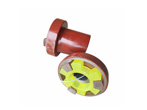
 Three-jaw coupling for pumpThe three-jaw coupling for pumps uses a number of non...
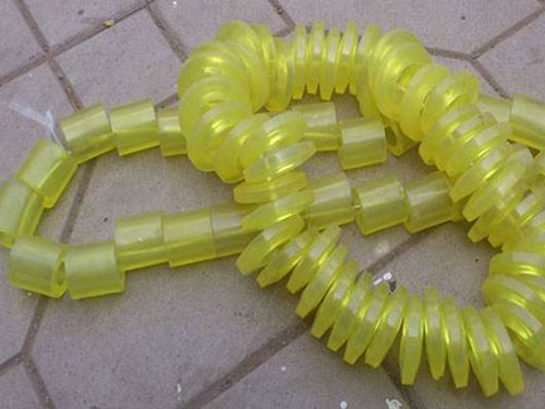 Elastic sleeveThe elastic sleeve uses a number of non-metal elastic...
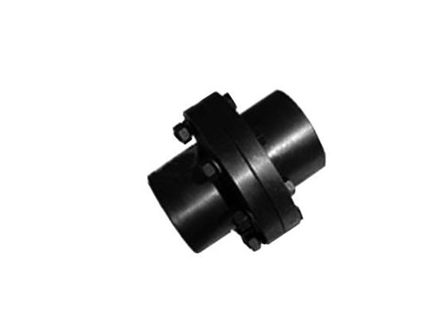 GY, GYS, GYH type rigid couplingThe surface roughness of the coupling means adding...
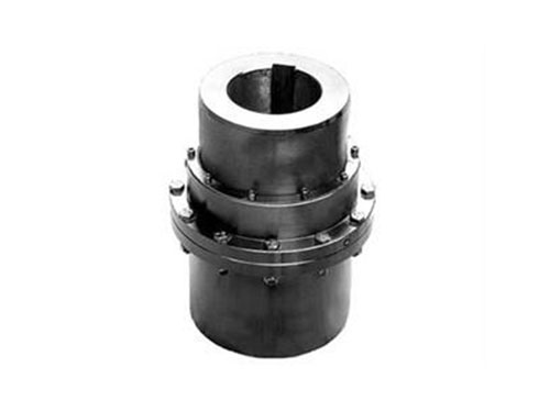 GICL type-drum gear couplingGICL type-drum gear coupling (JB/T 88...
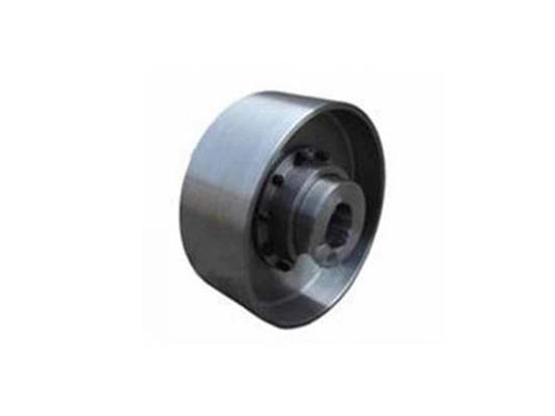 NGCL type drum gear coupling with brake wheelNGCL type drum gear coupling with brake wheel...
The problem solution of the coupling and the operation problem of the pump coupling
In the process of daily use, there should be problems with the coupling. What are the general problems?How to solve the problem?Let's tell everyone about it.
1. The axial displacement of the gear ring of the coupling is large, even unable to mesh.
2. There is a broken tooth in the coupling.
3. The coupling bolts are broken.
4. The tooth surface of the coupling is severely damaged.
The reasons for these failures mainly include the following two aspects:
1. The coupling of lifting accessories is short of oil or lack of oil.Or improper use of grease causes calcification of the grease, resulting in no lubrication between the tooth surfaces, or poor lubrication, causing serious wear on the tooth surfaces.
Treatment method: As long as the new grease is replaced, qualified grease is injected on time to prevent oil leakage, and the amount of oil is sufficient, it can be avoided.
2. The horizontality and coaxiality errors of the two shafts are too large to be compensated by the coupling, so that the shaft teeth and the internal teeth mesh inaccurately, causing local contact and generating additional torque.
Solution: This kind of failure is difficult to handle, and production needs to be stopped.That is, realign or realign the reducer, or realign the drum.At first, locate the position with large deviation error, and first measure the coupling, that is, measure the levelness of the main shaft, the coaxiality of the main shaft and the coaxiality of the reducer main shaft, and re-level and align it according to the quality scale. T can.
The fixing method of the coupling is shaft shoulder, shaft ring, shaft extension and shaft sleeve.Round nuts, shaft end buckles, shaft shoulders, shaft rings, shaft extensions, etc. have the characteristics of simple structure, positioning, and ability to withstand large axial forces.They are commonly used to locate gears, sprockets, pulleys, couplings and bearings.The sleeve has simple structure, positioning, no slot on the shaft, no thread drilling, and does not affect the fatigue strength of the shaft.Generally, it is used when the gap between parts is small, so as not to increase the weight of the structure. The high-speed rotation of the shaft is not suitable for use.The round nut is fixed, easy to disassemble and assemble, and can bear larger axial force.Due to the thread cutting on the shaft, the fatigue strength of the shaft is reduced.Double round nuts and stop washers are usually used to fix shaft end parts.When the distance between the parts is large, a round nut can be used instead of the sleeve to reduce the structural weight.
The market demand for pump couplings is large, and its quality requirements are getting higher and higher. For various reasons, the center of mass or inertial main shaft of pump couplings does not coincide with the axis of rotation, which will produce unbalanced centrifugal inertia during operation. The phenomenon of force, centrifugal inertia couple force and dynamic deflection (vibration shape) is called the unbalance phenomenon of the rotor. This unbalance phenomenon will inevitably cause the vibration of the shaft system, thereby affecting the normal operation and service life of the machine, so it needs Pay attention.The degree of unbalance (unbalance U) is usually expressed by the product mr of the mass m of the rotor and the distance r from the center of mass to the axis of rotation of the rotor, which is called the product of mass diameter.It is also expressed by the product of mass diameter per unit mass, called the eccentricity e (not geometrically eccentric.) The product of mass diameter mr is a relative quantity related to the mass of the rotor, while the eccentricity e is a value that has nothing to do with the mass of the rotor. The corresponding amount.The former is relatively intuitive and is often used for specific balancing operations of a given rotor. The latter is used to measure the pros and cons of the rotor balance or to check the balance accuracy. The balance grade standard of the pump coupling is evaluated by e.For a flexible rotor, use the mode eccentricity (the nth mode) en=Un/mn, and Un and mn are the nth mode and the first mode quality respectively.
Introduction to the problems and functions of pump couplings in operation:
XNUMX. The positive pressure of the centrifugal friction block installed on the swing arm of the pump coupling on the friction wheel is also increasing, and the friction torque gradually increases and forms a running effect.
XNUMX. The rotation of the prime mover of the pump coupling drives the swing arm to rotate, and it is thrown out under the action of centrifugal force, as the motor speed increases.
XNUMX. When the pump coupling is under severe overload or locked-rotor conditions, the torque at the load end is greater than the friction torque, and the centripetal force received by the centrifugal friction block is reduced, resulting in a reduction in the force on the slider, and the pump coupling plays a protective role .
XNUMX. When the load of the pump coupling increases or decreases sharply, the friction block and the friction wheel produce intermittent relative movement, thereby forming an alternating impact load, which repeatedly impacts the output sleeve of the pump coupling Match the joint surface with the input shaft of the reducer, thereby damaging the joint surface.
When the pump is aligned with the coupling, it should be adjusted in the vertical direction.The thickness of the front and rear foot pads can be calculated from the three-point detection data to detect the offset of the two axes.The outer edge diameter of the pump coupling at the movable end plus the distance from the outer edge of the pump coupling to the center of the axial dial gauge rod hole; the distance from the end face of the pump coupling at the movable end to the center of the front foot bolt at the movable end ; The distance between the front and rear bolt centers of the movable end.From the above data, the thickness of the front and rear foot pads can be known.If the motor is higher than the fixed end, shims should be reduced; if the motor is lower than the fixed end, shims should be added.After adjusting the vertical direction, the detection data of each point has changed. It should be reset at the 1 point position, and the data of 2 and 3 points should be measured again.After adjustment, you only need to check whether the sum is within the allowable error range.