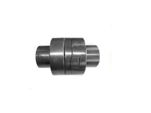
 SL cross slider couplingCross slider coupling is also known as metal slider...
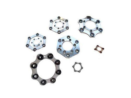 Diaphragm coupling diaphragmDiaphragm couplings have a wide range of applications...
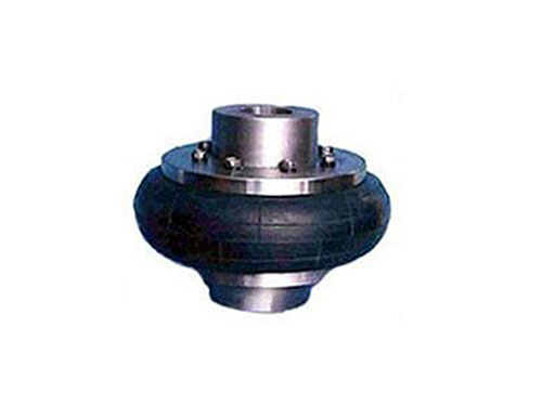 Tire coupling for LLB metallurgical equipmentTire coupling for LLB metallurgical equipment belongs to...
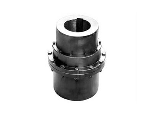 GICL type-drum gear couplingGICL type-drum gear coupling (JB/T 88...
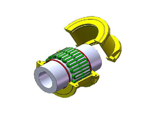 JS type housing radial mounting type couplingSelection of JS type housing radial mounting type coupling...
What errors will appear when inspecting drum gear couplings?
Couplings can be divided into two categories: rigid couplings and flexible couplings.
Rigid couplings do not have the ability to buffer and compensate for the relative displacement of the two axes, and require strict alignment of the two axes. However, this type of coupling has simple structure, low manufacturing cost, convenient assembly and disassembly and maintenance, and it can be determined that the two axes have a high The centering property of, the transmission torque is large, and it is widely used.Commonly used are flange couplings, sleeve couplings and clamp couplings.
Flexible couplings can be divided into flexible couplings without elastic elements and flexible couplings with elastic elements. The former type only has the ability to compensate the relative displacement of the two axes, but it cannot buffer and reduce vibration. The common ones are slippery. Block couplings, gear couplings, universal couplings and chain couplings, etc.; the latter type contains elastic elements, which not only has the ability to compensate for the relative displacement of the two axes, but also has buffering and damping functions. However, the transmitted torque is limited by the strength of the elastic element, and is generally not as good as the flexible coupling without elastic elements. Commonly used are elastic sleeve pin couplings, elastic pin couplings, plum-shaped couplings, and tire-type couplings. Couplings, serpentine spring couplings and reed couplings, etc.
Drum-shaped gear couplings use parallel or spiral grooving systems to adapt to various deviations and accurately transmit torque. They usually have good performance and price advantages. In many practical applications of stepping and servo systems, they are integrated The design of the drum gear coupling achieves the advantages of zero-clearance torque transmission and no maintenance.There is a continuous multi-turn long slot. This coupling has excellent elasticity and small bearing load. It can withstand various deviations. It is more suitable for correcting deflection and axial deviation, but dealing with eccentricity The ability of the coupling is relatively poor, because it is necessary to bend the spiral groove in two different directions at the same time, which will generate a large internal pressure, which will cause the premature damage of the coupling.The long spiral groove coupling can be easily bent under various deviations, but it has the same effect on the rigidity of the coupling under torsional load, and the excessive swing clearance under torsional load will affect the coupling. The accuracy of the shaft and weaken its overall performance.
If the coupling is used on a high-torque machine, the selected aperture must be 5mm smaller than the aperture indicated in the above table. (Because at the moment when the driving shaft starts, a large impact load will be generated on the coupling. The actual instantaneous torque is much greater than the rated torque of the coupling.)
When the coupling is in use, when the actual speed is close to the high speed limit, please check the dynamic balance in time.
XNUMX. What errors will appear when inspecting drum gear couplings?
1. Check the measured form and position error of the coupling.When measuring form and position errors, pay attention to the measurement datum, and pay attention to the elements marked with the principle of tolerance and the principle of large entity.For the elements that are not marked with geometric tolerances on the paper, the inspectors can find the tolerance values and measure them according to the national or enterprise standards as needed.
2. Check the dimensional accuracy of the coupling.When checking the dimensional accuracy of the coupling, check the drawings, processes and technical conditions.Generally, check the shape and size first. When the shape is complicated, the specific data is included in the table textile and omitted.
3. When inspecting parts, first check the specifications and grades of the materials used in the parts with reference to the title bar of the drawings and process documents, and check the grain direction and status of the plates.Dimensional inspection is carried out after passing the test.
4. Check the specific parameters of the coupling.For example: check the geometry of the coupling against the front view and other views; check whether the position of each element is correct, such as holes, grooves, etc.; check the surface roughness and surface quality.
XNUMX. Introduction to the external tooth function of the drum-shaped gear coupling
1. The drum-shaped gear coupling is a rigid flexible coupling. It consists of an inner gear ring with the same number of teeth and a flange half coupling connected to the outer teeth. The outer teeth are divided into straight teeth and drum teeth. The coupling can allow a larger angular displacement, can improve the contact conditions of the teeth, increase the torque transmission capacity, and prolong the service life.
2. The external teeth of the drum-shaped gear coupling are divided into straight teeth and drum teeth. The drum-shaped gear coupling can allow large angular displacements, improve the contact conditions of the teeth, increase the ability to transmit torque, and extend the service life. When there is angular displacement, the contact state along the tooth width.
3. The drum gear coupling is composed of an inner gear ring with the same number of teeth and a flange half coupling connected with the outer teeth. The outer teeth are divided into straight teeth and drum teeth. The so-called drum teeth are made of spherical surfaces. The spherical center is located on the gear shaft, and the tooth surface clearance is larger than that of ordinary gears. The drum gear coupling can allow a larger angular displacement, which can improve the contact conditions of the teeth, increase the torque transmission capacity, and prolong the service life.