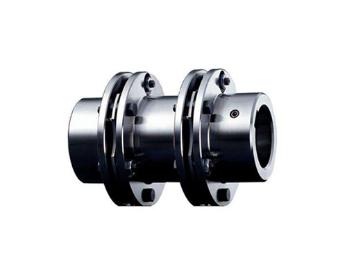
 JMⅡJ Type Intermediate Shaft Type Diaphragm CouplingJMⅡJ Type Intermediate Shaft Type Diaphragm Coupling...
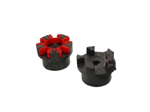 XL type star elastic couplingXL type star elastic coupling and other coupling...
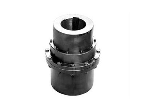 GICL type-drum gear couplingGICL type-drum gear coupling (JB/T 88...
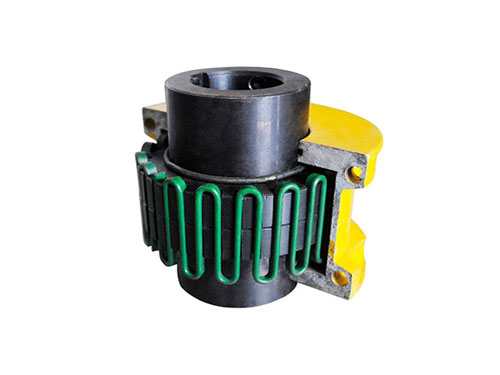 JSB type axial mounting couplingThe general material of J-type axial installation coupling...
 FZ type double fulcrum square bottom plate rackFZ type double fulcrum square bottom plate rack series is suitable for...
The characteristics and common failure causes of drum gear couplings
Drum gear coupling has the following characteristics:
XNUMX. The drum-shaped tooth surface enables the contact conditions of the inner and outer teeth to avoid the disadvantages of squeeze and stress concentration at the edge of the straight tooth under the condition of angular displacement. At the same time, it reduces the friction and wear of the tooth surface, reduces noise and maintains The cycle is long.
XNUMX. The tooth end of the outer gear sleeve is in the shape of a horn, which makes the assembly and disassembly of the inner and outer gears convenient.
XNUMX. Good airtightness, convenient use, loading and unloading, and maintenance; suitable for smelting, steel rolling, heavy machinery, steam turbine, petrochemical industry, shipbuilding and other industries.
15. Carrying.Under the same outer diameter of the inner gear sleeve and the large outer diameter of the coupling, the load-bearing capacity of the drum gear coupling is on average 20% to XNUMX% higher than that of the straight gear coupling;
1.5. Large angular displacement compensation.Because the outer gear sleeve is a drum-shaped tooth, the coupling can avoid angular contact between the inner and outer gears when working, allowing the axis of the two shafts to have an angular displacement of ± 2°, and it can also work when the angular displacement is 3° to 1°.It is generally recommended to allow an angular displacement of 30°2', 30°XNUMX'.
Analysis of common failure causes of drum gear couplings at the production site:
1. The connection between the rolling mill of the bar and wire rod and the reduction box in the L steel equipment is mostly a through-type drum gear coupling. The structure of the reducer end of the coupling is shown in Figure XNUMX.The drum gear coupling includes a shaft, an outer gear sleeve, an inner gear ring, and a connecting disk. The connecting disk is connected to the end surface of the output shaft of the reducer to be assembled by a locking bolt, and the inner gear ring is set on the to be assembled through a spline. The output shaft of the reducer is pressed on the connecting plate, the outer gear sleeve is sleeved on the shaft through a spline and has an interference fit with the shaft, and the outer gear sleeve is suspended on the inner gear ring through a pressure plate and a locking bolt and is connected with The teeth of the inner ring gear mesh.
XNUMX. When the drum gear coupling of the above structure is in use, the entire coupling is pressed on the connecting plate fixedly connected to the end surface of the output shaft of the reducer through the outer gear sleeve and the inner gear ring, almost the entire drum gear The gravity of the type coupling is concentrated on the connecting plate.When the roll is rolling the blank, it is affected by the impact of the blank and the vibration of the upper and lower rolls. The locking bolts connecting the connecting plate and the reducer are subjected to both tensile and shearing forces. The bolts are locked under long-term rotation of the drum gear coupling. It is easy to be pulled or sheared, and the connecting disc is located in the inner gear ring and cannot be found at any time. After all the locking bolts fail, the entire drum gear coupling is separated from the output shaft of the reducer, causing The equipment shutdown seriously affected the subsequent processing procedures.
XNUMX. From the perspective of structure and usage, the main reason for the above failures is that the rolls of the rolling mill have been repeatedly used for many times, and the shaft diameter size has changed, and the drum gear coupling has changed the inclination of the shaft under rotation. Because the gap between the connecting disc and the inner gear is too small, the inner gear radially presses the connecting disc when compensating for the gap of the spline shaft. When the roll is rolling the blank, the spline shaft always swings, and the swing makes the connection The collision between the outer surface of the disc and the inner surface of the inner gear ring aggravates the shearing force of the locking bolt and the connecting ring sleeve, resulting in failure of the connecting bolt of the connecting disc due to shearing.
Therefore, this article aims at the shortcomings of the analysis of the above-mentioned drum gear coupling failure, in order to increase the connection between the connecting plate and the output shaft of the reducer, reduce the tension or shear force on the locking bolt, and avoid the drum gear The type coupling is pulled or sheared when rotating, which reduces the equipment failure of the vertical rolling mill and further increases the production rate. An improved plan for the connecting plate is proposed.
Drum-shaped gear couplings have been paid more and more attention in production practice.It can compensate the angle formed by the misalignment of the axes of the two coupling shafts, the axial and radial installation errors, and allow the displacement of the two shafts.The rotation direction can be clockwise or counterclockwise. It can be driven horizontally or vertically under a special structure. It has great advantages in general machine manufacturing.Especially in the following special conditions, it is excellent: intermittently moving machinery; machinery with heavy transmission load; two coupling shafts have large adjustment errors and so on.Based on the above characteristics, drum gear couplings are commonly used in metallurgy, mining, steel rolling and other departments.
The structure of the drum gear coupling is basically symmetrical, and the two outer gear sleeves can be press-fitted or hot-fitted to the shaft head through a key connection.The tooth surface of the outer gear sleeve is curved in the length direction, which is processed by the template using the profiling method.From the direction of the tooth tip, the teeth on the outer gear sleeve are drum-shaped teeth, and the tooth thickness gradually decreases from both sides, while the teeth on the inner gear ring that mesh with it are linear teeth.Because the tooth tip and tooth surface of the external gear sleeve are arc-shaped, the entire coupling is double articulated and flexible.In this way, the large deflection angle between the two axes can be adapted, and thin oil lubrication or dry oil lubrication can be used.The drum gear coupling has a compact structure, small size, weight, volume and moment of inertia, all parts are round, and the unbalanced moment is also small.
The bearing capacity and allowable offset or swing angle of the drum gear coupling are directly related to the radius of curvature (curvature) of the tooth.From the perspective of increasing the load-bearing capacity, the larger the radius of curvature, the better, and in terms of increasing the allowable swing angle, the smaller the radius of curvature, the better.The arc on the side of the drum tooth is naturally formed when the hob moves along the arc during machining, so the radius of the infeed arc determines the radius of curvature of the tooth.
The small torque of the drum gear coupling and the transmission of the shaft system mainly require the coupling to have a relatively good transmission accuracy. A flexible coupling with a non-metal elastic element can be used.The large torque of the drum-shaped gear coupling and the transmission of the power transmission shaft system have no requirements for transmission accuracy. When the speed is high, avoid the gap between the elastic coupling of the metal elastic element and the movable element. For the flexible coupling, you can choose a diaphragm coupling with good transmission accuracy.
Next:Nothing