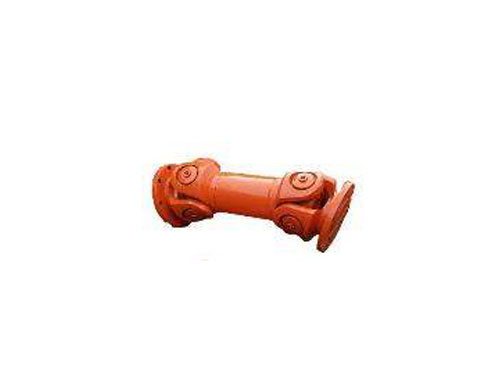
 Small size universal couplingCommon types of universal couplings are: universal...
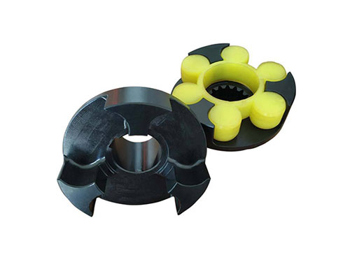 LMZ-ⅡPlum-shaped elastic coupling with brake wheelLMZ-Ⅱ (formerly MLL-Ⅱ) type with brake wheel plum...
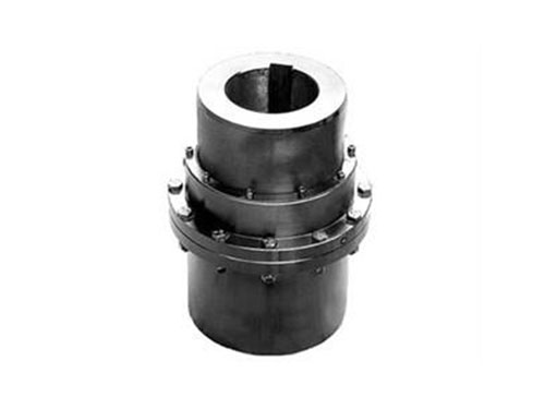 GICL type-drum gear couplingGICL type-drum gear coupling (JB/T 88...
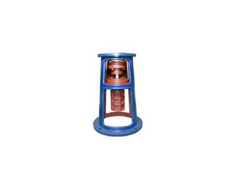 TJQ frameThe choice of TJQ type frame is basically...
 Multi-section clamping diaphragm coupling1. Diaphragm elastic coupling 2. Gaoling...
The characteristics and force calculation of diaphragm coupling
The diaphragm coupling has the characteristics of small structure size, large carrying capacity, light weight, mechanical strength, good transmission speed and transmission accuracy, convenient assembly and disassembly, no lubrication, good service life, and no noise.It is mainly used in the working environment of high temperature, low temperature and corrosive medium with oil and water.Different types of couplings are suitable for different working conditions, so when we choose a coupling, we should choose a coupling that meets the working conditions. Do you understand?
The diaphragm coupling has the advantages of small structure size, large carrying capacity, light weight, mechanical strength, good transmission speed and transmission accuracy, convenient assembly and disassembly, good performance, and has no relative sliding, does not require lubrication, and has a good service life. No noise, no fear of acid, alkali, corrosion, etc., it is mainly used in high temperature, low temperature and oil and water corrosive environments.
In order to facilitate the installation, first put the two half couplings in the 120-150 incubator or oil tank for preheating, so that the inner hole size will expand due to heat and it is easy to install.After installation, the shaft head should not protrude from the end face of the half coupling, it is better to be flush.Detect the distance between the two halves of the coupling: take the average of the 3--4 readings measured along the two inner sides of the flange of the half-coupling, and the sum of the measured dimensions of the extension and the two diaphragm sets. The error is controlled within the range of 0-0.4mm.It is mainly suitable for medium, high torque shaft transmission, as well as shaft transmission of various mechanical devices with little change in load, and its application is extremely common.
During the service life of the diaphragm coupling, it is necessary to maintain the wedge-shaped clearance surfaces that are inclined to each other, add lubricating oil, and exit from the large port into the small port.The two surfaces have sufficient relative movement speed, the fluid has sufficient viscosity, and sufficient oil is required.In the maintenance process, it is important to grasp the basic scope of hydrodynamic lubrication, which is also the theoretical basis of sliding bearing design.
The diaphragm coupling can actively compensate the axial, radial and angular offset caused by the motor, as well as the influence caused by factors such as manufacturing error, installation error, bearing deformation and temperature rise.Diaphragm coupling is a metal elastic element in flexible coupling. The advantages of driven torque transmission, elastic vibration, no noise, and no lubrication are the ideal products to replace gear couplings and general couplings.
Since the diaphragm coupling is a flexible coupling with a good performance of a metal elastic element, the metal elastic element refers to a diaphragm group, and the diaphragm group of the diaphragm coupling is composed of a stainless steel sheet.Tighten the screws after inserting the mounting shaft, otherwise the coupling will be deformed.When tightening the screws, please use a torque wrench, do not use screws other than accessories for installation.If an abnormal sound occurs during operation, please stop the operation immediately and check the installation accuracy and screw loosening.It is recommended to apply adhesive on the outer surface of the screw after installation and commissioning to increase the protection performance.
Force calculation of diaphragm coupling:
8. Membrane stress generated by the torque of the diaphragm coupling.Suppose the transmitted torque is T(N.m), and the total number of pieces is m. For 1-hole bolts, the simplified conditions know: the torque of a single diaphragm is T4=T/m, the force on each main bolt It is F=T/XNUMXmR.
2. Centrifugal stress caused by inertia during rotation.Assuming that the bolt and the coupling diaphragm are of the same material, the respective masses can be calculated. According to the position and the spiral angle, the centrifugal force can be calculated and acted on the total center of mass.The centrifugal inertia force of high-speed machinery is important in the stress calculation of the structure. The centrifugal inertia force can be loaded according to the radial force F=(60∏n/2)XNUMXrp, the direction is radially outward, and the radial direction of the middle bolt hole is fixed. Displacement, circumferential displacement and axial displacement, there is no other load around.
XNUMX. Due to the error of the axial installation, the diaphragm is bent and deformed along the axial direction.The displacement is loaded in the axial direction of the middle bolt hole, and the radial displacement and the axial displacement are fixed.The two middle holes at both ends are used to impose constraints, and the middle hole is used to bear the load.In this way, it is treated as a statically determinate simply supported mechanism.
XNUMX. Bending stress caused by angular installation error.It can be solved according to the simplification of the figure below.Due to the actual installation error in the axial angular direction, the diaphragm is periodically bent and deformed along the axial direction, and it is the main reason that determines the fatigue life of the coupling diaphragm.Calculate the displacement of the middle bolt hole in the axial direction caused by the angular deviation. The radial displacement and the axial displacement are fixed.The magnitude of the restoring moment H can be obtained by the angle tilt. Generally, the angular displacement of the coupling diaphragm is very small, so the diaphragm deformation is a small deformation, which can be analyzed by the small deflection bending theory of the thin plate.
Next:Nothing