Product Description
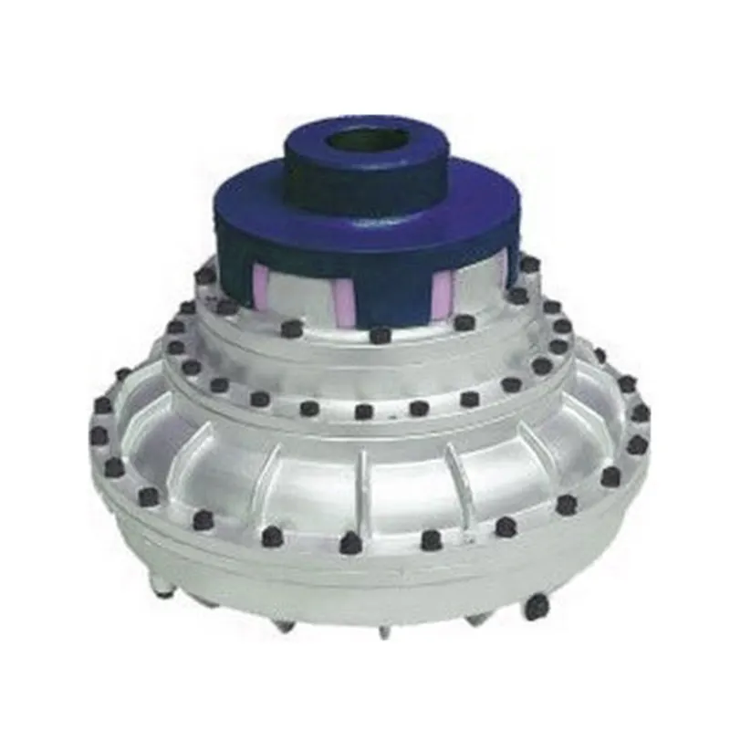
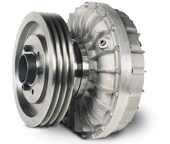
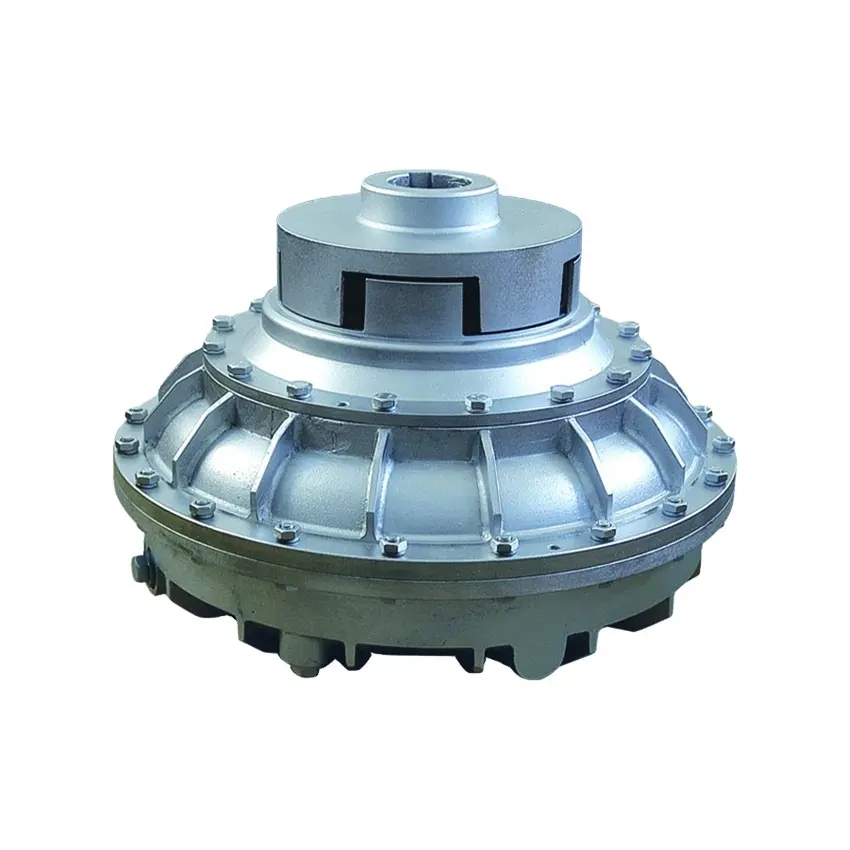
Flexible flex Fluid Chain Jaw flange Gear Rigid Spacer PIN HRC MH NM universal Fenaflex Oldham spline clamp tyre grid hydraulic servo motor shaft Coupling
Product Description
The function of Shaft coupling:
1. Shafts for connecting separately manufactured units such as motors and generators.
2. If any axis is misaligned.
3. Provides mechanical flexibility.
4. Absorb the transmission of impact load.
5. Prevent overload
We can provide the following couplings.
| Rigid coupling | Flange coupling | Oldham coupling |
| Sleeve or muff coupling | Gear coupling | Bellow coupling |
| Split muff coupling | Flexible coupling | Fluid coupling |
| Clamp or split-muff or compression coupling | Universal coupling | Variable speed coupling |
| Bushed pin-type coupling | Diaphragm coupling | Constant speed coupling |
Company Profile
We are an industrial company specializing in the production of couplings. It has 3 branches: steel casting, forging, and heat treatment. Main products: cross shaft universal coupling, drum gear coupling, non-metallic elastic element coupling, rigid coupling, etc.
The company mainly produces the industry standard JB3241-91 swap JB5513-91 swc. JB3242-93 swz series universal coupling with spider type. It can also design and produce various non-standard universal couplings, other couplings, and mechanical products for users according to special requirements. Currently, the products are mainly sold to major steel companies at home and abroad, the metallurgical steel rolling industry, and leading engine manufacturers, with an annual production capacity of more than 7000 sets.
The company’s quality policy is “quality for survival, variety for development.” In August 2000, the national quality system certification authority audited that its quality assurance system met the requirements of GB/T19002-1994 IDT ISO9002:1994 and obtained the quality system certification certificate with the registration number 0900B5711. It is the first enterprise in the coupling production industry in HangZhou City that passed the ISO9002 quality and constitution certification.
The company pursues the business purpose of “reliable quality, the supremacy of reputation, commitment to business and customer satisfaction” and welcomes customers at home and abroad to choose our products.
At the same time, the company has established long-term cooperative relations with many enterprises and warmly welcomes friends from all walks of life to visit, investigate and negotiate business!
How to use the coupling safely
The coupling is an intermediate connecting part of each motion mechanism, which directly impacts the regular operation of each motion mechanism. Therefore, attention must be paid to:
1. The coupling is not allowed to have more than the specified axis deflection and radial displacement so as not to affect its transmission performance.
2. The bolts of the LINS coupling shall not be loose or damaged.
3. Gear coupling and cross slide coupling shall be lubricated regularly, and lubricating grease shall be added every 2-3 months to avoid severe wear of gear teeth and serious consequences.
4. The tooth width contact length of gear coupling shall not be less than 70%; Its axial displacement shall not be more significant than 5mm
5. The coupling is not allowed to have cracks. If there are cracks, it needs to be replaced (they can be knocked with a small hammer and judged according to the sound).
6. The keys of LINS coupling shall be closely matched and shall not be loosened.
7. The tooth thickness of the gear coupling is worn. When the lifting mechanism exceeds 15% of the original tooth thickness, the operating mechanism exceeds 25%, and the broken tooth is also scrapped.
8. If the elastic ring of the pin coupling and the sealing ring of the gear coupling is damaged or aged, they should be replaced in time.
Certifications
Packaging & Shipping
/* January 22, 2571 19:08:37 */!function(){function s(e,r){var a,o={};try{e&&e.split(“,”).forEach(function(e,t){e&&(a=e.match(/(.*?):(.*)$/))&&1
Fluid Coupling and Smooth Power Transmission during Starting and Stopping
A fluid coupling is designed to facilitate smooth power transmission during the starting and stopping phases of machinery and equipment. It achieves this by utilizing the principle of hydrodynamic torque transmission through a fluid medium.
Starting Phase: When power is initially supplied to the input shaft of the fluid coupling, the impeller (also known as the pump) begins to rotate, imparting energy to the fluid inside the coupling. As the fluid gains kinetic energy, it starts moving outward towards the turbine (also called the driven element) due to centrifugal force.
The kinetic energy of the moving fluid causes the turbine to start rotating, transmitting torque to the output shaft. During this starting phase, there is a slight time lag, known as the “slip,” between the impeller and the turbine. However, as the fluid coupling reaches its operational speed, the slip reduces, and the turbine matches the speed of the impeller, resulting in smooth power transmission from the input to the output shaft.
The fluid coupling’s ability to control the slip ensures a gradual and controlled acceleration of the driven equipment, minimizing stress on the drivetrain components and preventing sudden shock loads.
Stopping Phase: When power to the input shaft is reduced or cut off, the impeller slows down, and the kinetic energy in the fluid decreases. As a result, the fluid moves away from the turbine towards the center of the coupling, reducing the torque transmission between the input and output shafts.
This characteristic of the fluid coupling aids in smoothly decelerating the connected equipment, preventing sudden jolts or jerks during the stopping process. The ability to control the slip during deceleration ensures that the driven machinery comes to a gradual and controlled stop, enhancing safety and protecting the equipment from damage.
The combination of hydrodynamic torque transmission and the ability to control the slip makes fluid couplings ideal for applications where smooth power transmission during starting and stopping is essential. Industries such as mining, construction, metal processing, marine propulsion, and power generation benefit from the reliable and efficient performance of fluid couplings in various machinery and equipment.

Real-World Case Studies: Improved Performance with Fluid Couplings
Fluid couplings have been widely adopted in various industries, and numerous real-world case studies demonstrate their positive impact on performance and efficiency. Here are a few examples:
Case Study 1: Mining Conveyor System
In a large mining operation, a conveyor system used to transport heavy loads of ore experienced frequent starts and stops due to fluctuating material supply. The abrupt starting and stopping led to significant wear and tear on the conveyor components, causing frequent breakdowns and maintenance downtime.
After installing fluid couplings at critical points in the conveyor system, the soft start and stop capability of the fluid couplings significantly reduced the mechanical stress during operation. This led to a smoother material flow, reduced conveyor wear, and extended equipment life. Additionally, the fluid couplings’ overload protection feature prevented damage to the conveyor during peak loads, ensuring uninterrupted production.
Case Study 2: Marine Propulsion System
In a marine vessel equipped with traditional direct drive systems, the crew faced challenges in maneuvering the ship efficiently. The fixed propeller arrangement made it challenging to control the vessel’s speed and direction accurately, leading to increased fuel consumption and decreased maneuverability.
By retrofitting the vessel’s propulsion system with fluid couplings, the ship’s performance improved significantly. The fluid couplings allowed for flexible and smooth speed control, enabling precise maneuvering and reduced fuel consumption. The ability to adjust the load on the propeller enhanced the vessel’s overall efficiency, resulting in reduced operating costs and improved environmental sustainability.
Case Study 3: Industrial Pumping Station
In an industrial pumping station, the constant starting and stopping of the pumps caused water hammer and pressure surges within the pipeline network. The sudden hydraulic shocks led to pipe bursts, valve failures, and increased energy consumption.
After implementing fluid couplings in the pump drive systems, the pumps could be softly started and stopped. The fluid couplings’ torque control capabilities ensured a gradual increase in pump speed, eliminating water hammer and pressure surges. As a result, the pumping station’s reliability improved, maintenance costs decreased, and the energy consumption reduced due to smoother pump operations.
These case studies demonstrate the positive effects of using fluid couplings in various applications. They highlight how fluid couplings contribute to improved performance, reduced mechanical stress, enhanced control, and cost savings in industrial machinery and systems.
“`
Comparison: Fluid Coupling vs. Torque Converter
Fluid couplings and torque converters are both hydrodynamic devices used in automotive and industrial applications to transmit power between an engine and a driven load. While they share some similarities, they also have distinct differences:
- Function: The primary function of both fluid couplings and torque converters is to transmit rotational power from the engine to the transmission or driven load. They allow for smooth power transmission and provide a degree of isolation between the engine and the load.
- Construction: Both devices consist of an impeller, a turbine, and a housing filled with hydraulic fluid (usually oil). The impeller is connected to the engine’s crankshaft, the turbine to the transmission/input shaft, and the housing is shared between the two.
- Torque Transmission: In a fluid coupling, the power is transmitted purely through hydrodynamic principles. The impeller accelerates the fluid, which then drives the turbine. However, there is no torque multiplication, and the output speed is always slightly less than the input speed. On the other hand, a torque converter can provide torque multiplication due to its stator, which redirects the fluid flow and increases the torque transmitted to the turbine.
- Lock-up Clutch: Some torque converters have a lock-up clutch that can mechanically connect the impeller and the turbine at higher speeds. This effectively eliminates the slip between the two elements and increases overall efficiency, similar to the operation of a fluid coupling at higher speeds.
- Automotive Use: Torque converters are commonly used in automatic transmissions in vehicles, while fluid couplings were more prevalent in older manual transmissions. However, modern manual transmissions generally use clutch systems instead of fluid couplings.
- Efficiency: Fluid couplings are generally more efficient than torque converters, especially at higher speeds. Torque converters can experience efficiency losses due to fluid slippage and the operation of the stator.
- Applications: Fluid couplings find applications in various industrial machinery, such as conveyors, pumps, and crushers, where the priority is smooth power transmission and overload protection. Torque converters are primarily used in vehicles, offering the benefit of automatic gear shifting and torque multiplication during acceleration.
Overall, both fluid couplings and torque converters play essential roles in power transmission, but their specific design and application characteristics determine their suitability for different use cases.


editor by CX 2024-04-26
China manufacturer Flexible Shaft Chain Coupling Rigid Bellow Grid Beam Tyre Roller Fluid Jaw Compliant Mechanism Oldham Coupler Rag Joint Universal Joint Dis Motor HRC Coupling
Product Description
Manufacturer of Couplings, Fluid Coupling, JAW Coupling, can interchange and replacement of lovejoy coupling and so on.
A coupling can interchange and replacement of lovejoy coupling is a device used to connect 2 shafts together at their ends for the purpose of transmitting power. The primary purpose of couplings is to join 2 pieces of rotating equipment while permitting some degree of misalignment or end movement or both. In a more general context, a coupling can also be a mechanical device that serves to connect the ends of adjacent parts or objects. Couplings do not normally allow disconnection of shafts during operation, however there are torque limiting couplings which can slip or disconnect when some torque limit is exceeded. Selection, installation and maintenance of couplings can lead to reduced maintenance time and maintenance cost.
/* January 22, 2571 19:08:37 */!function(){function s(e,r){var a,o={};try{e&&e.split(“,”).forEach(function(e,t){e&&(a=e.match(/(.*?):(.*)$/))&&1

Factors to Consider when Choosing between a Fluid Coupling and a VFD (Variable Frequency Drive)
When selecting between a fluid coupling and a VFD for a power transmission application, several factors should be taken into account:
- Speed Control Requirements: Consider whether variable speed control is essential for your application. VFDs are excellent for applications that require precise and flexible speed control, while fluid couplings typically offer limited speed control capabilities.
- Energy Efficiency: Evaluate the energy efficiency requirements of your system. VFDs can offer higher energy efficiency by allowing the motor to run at optimal speeds, whereas fluid couplings introduce some energy losses due to slip.
- Starting Torque: Examine the starting torque requirements of the driven load. Fluid couplings can provide high starting torque and smooth acceleration, which may be advantageous for applications with high inertia loads.
- Overload Protection: Consider the need for overload protection. Fluid couplings inherently provide some protection against shock loads by allowing slip, while VFDs may require additional protective mechanisms.
- Maintenance and Service: Evaluate the maintenance and service requirements of both systems. Fluid couplings are generally simpler and require less maintenance compared to VFDs, which involve electronic components.
- Cost: Compare the initial and long-term costs of both options. VFDs often have higher upfront costs but can provide significant energy savings in the long run, while fluid couplings may have lower initial costs but could lead to higher energy consumption.
Ultimately, the choice between a fluid coupling and a VFD depends on the specific needs of your application. Each option has its advantages and limitations, and a thorough analysis of the operating conditions and performance requirements will help determine the most suitable solution for your system.

Cost Implications of Using Fluid Couplings in Comparison to Other Power Transmission Methods
The cost implications of using fluid couplings in power transmission depend on various factors, including the application requirements, the size of the system, and the operational conditions. While fluid couplings offer several advantages, they may have different cost considerations compared to other power transmission methods like mechanical clutches, VFDs (Variable Frequency Drives), and direct mechanical drives.
1. Initial Investment:
The initial cost of a fluid coupling can be higher than that of a mechanical clutch or a direct mechanical drive. Fluid couplings contain precision components, including the impeller and turbine, which can impact their initial purchase price.
2. Maintenance Costs:
Fluid couplings are generally considered to have lower maintenance costs compared to mechanical clutches. Mechanical clutches have wear and tear components that may require more frequent replacements, leading to higher maintenance expenses over time.
3. Energy Efficiency:
Fluid couplings are highly efficient in power transmission, especially during soft-start applications. Their ability to reduce shock loads and provide a smooth acceleration can result in energy savings and operational cost reductions.
4. Space and Weight:
Fluid couplings are usually more compact and lighter than some mechanical clutches, which can be advantageous in applications with space constraints or weight limitations.
5. Specific Application Considerations:
The suitability and cost-effectiveness of fluid couplings versus other power transmission methods can vary based on specific application requirements. For example, in soft-start applications, fluid couplings may be the preferred choice due to their ability to reduce mechanical stress and protect connected equipment.
6. Lifespan and Reliability:
While the initial cost of a fluid coupling might be higher, their longevity and reliability can lead to lower overall life cycle costs compared to other power transmission methods.
In conclusion, the cost implications of using fluid couplings in power transmission depend on the particular application and the total cost of ownership over the equipment’s lifespan. Although fluid couplings may have a higher initial investment, their long-term reliability, energy efficiency, and lower maintenance costs can make them a cost-effective choice in many industrial applications.

Can Fluid Couplings be Retrofitted into Existing Machinery?
Yes, fluid couplings can be retrofitted into existing machinery in many cases. Retrofitting is a process of adding new components or technologies to existing equipment to improve its performance or functionality. Fluid couplings are versatile and can often be integrated into various industrial machines and power transmission systems.
The process of retrofitting a fluid coupling involves several steps:
- Evaluation: Before retrofitting, a thorough evaluation of the existing machinery is necessary. Engineers need to assess the machine’s design, power requirements, and other relevant factors to determine the suitability of a fluid coupling.
- Compatibility: Fluid couplings should be compatible with the existing machine’s shaft, motor, and driven equipment. If necessary, modifications may be required to ensure a proper fit.
- Installation: The installation process involves mounting the fluid coupling onto the machine’s shaft and connecting it to the motor and driven equipment.
- Alignment: Precise alignment of the fluid coupling is crucial for optimal performance and to avoid issues such as vibration and wear.
- Testing: After installation, the retrofitted system undergoes testing to ensure that it functions as intended and meets the desired performance goals.
Retrofitting fluid couplings can offer various benefits, including:
- Improved Energy Efficiency: Fluid couplings can enhance energy efficiency by reducing power losses and improving the overall power transmission system’s efficiency.
- Enhanced Protection: Fluid couplings provide protection against shocks and overloads, safeguarding the machinery and its components from damage.
- Reduced Maintenance: The smooth start and reduced stress on the machine during operation can lead to lower maintenance requirements and longer equipment lifespan.
- Soft Start: Fluid couplings offer a soft start, which reduces the mechanical stress on the machine during startup, extending its life and minimizing downtime.
However, it is essential to involve qualified engineers and technicians for the retrofitting process to ensure proper installation, alignment, and performance of the fluid coupling in the existing machinery.
editor by CX 2024-04-22
China Best Sales Flexible Fluid Chain Jaw Flange Gear Rigid Oldham Servo Motor Shaft Coupling
Product Description
|
Product Name |
Flexible Fluid Chain Jaw Flange Gear Rigid Oldham Servo Motor Shaft Coupling |
|
Material |
Aluminum alloy,stainless steel |
|
Surface treatment |
Natural color anode |
|
Customized service |
Support light customization and logo customization |
| Size | To be customized |
|
Remarks |
The default engraving brand name and size of the product. If you need not engraving, please contact the customer service for comments |
| Packaging Details | Carton box with anti-static package,carton plus with wooden case. |
| Main Products | Shaft Parts, Timing Belt Pulley, Gears, CNC Machining Parts, Sheet Metal Fabrication |
| Certifications(2) | ISO9001:2015, IPMS |
| Applicable Industries | Building Material Shops, Manufacturing Plant, Food & Beverage Factory, Farms |
| Supply Ability | 100000 Piece/Pieces per Month |
| Dimension | oem provided |
| Surface finish | anodized |
| Lead Time | 25 days |
| Application | Furniture,cabinet |
| Custom | OEM and ODM services are welcome,we can make cutom LOGO and products according to customer’s requests. |
| Quality control Our | Finished product inspection,Warranty available |
| service | Swiss machining;deburring;lathe/turning;5 axis;micromachining |
| Color |
silver,gold,black,red,bulue,and according to the customer requests. |
/* January 22, 2571 19:08:37 */!function(){function s(e,r){var a,o={};try{e&&e.split(“,”).forEach(function(e,t){e&&(a=e.match(/(.*?):(.*)$/))&&1
What are the Differences between Fluid Couplings and Mechanical Clutches?
Fluid couplings and mechanical clutches are both components used in power transmission systems, but they operate on different principles and have distinct characteristics:
- Operating Principle:
- Fluid Coupling: A fluid coupling uses hydraulic fluid to transmit torque. It consists of an impeller and a runner immersed in a fluid-filled chamber. When the input shaft (driving member) rotates, it imparts motion to the fluid, which in turn drives the output shaft (driven member).
- Mechanical Clutch: A mechanical clutch relies on physical contact between friction surfaces to transmit torque. When engaged, the clutch plates or discs press against each other, creating a mechanical link between the input and output shafts.
- Slippage:
- Fluid Coupling: Fluid couplings allow a certain degree of slippage between the input and output shafts. This slippage provides a smooth start and helps protect the machinery from shock loads.
- Mechanical Clutch: Mechanical clutches have minimal slippage when engaged, providing a direct and rigid connection between the input and output shafts.
- Control:
- Fluid Coupling: Fluid couplings provide automatic torque transmission without the need for manual engagement or disengagement.
- Mechanical Clutch: Mechanical clutches require manual actuation to engage or disengage, allowing for precise control over power transmission.
- Heat Dissipation:
- Fluid Coupling: Fluid couplings dissipate heat generated during operation, which helps prevent overheating of the system.
- Mechanical Clutch: Mechanical clutches may generate more heat due to friction, requiring additional cooling mechanisms in high-power applications.
- Applications:
- Fluid Coupling: Fluid couplings are commonly used in heavy machinery, such as mining equipment, crushers, and conveyors, where shock absorption and smooth starts are crucial.
- Mechanical Clutch: Mechanical clutches are prevalent in applications where precise engagement and disengagement are required, such as automotive transmissions and manual industrial machinery.
While both fluid couplings and mechanical clutches serve the purpose of transmitting torque, their different operating principles and features make them suitable for specific applications and operating conditions.
Fluid Couplings in Hydraulic Drive Systems
Yes, fluid couplings can be used in hydraulic drive systems to transmit power and control the speed of driven components. In hydraulic drive systems, fluid couplings act as a torque converter, providing a smooth and gradual transfer of power between the input and output shafts.
The basic principle of a fluid coupling remains the same whether it is used in a mechanical drive system or a hydraulic drive system. The fluid coupling consists of an input impeller connected to the prime mover (such as an electric motor or an engine) and an output runner connected to the driven component.
When the prime mover is activated, it drives the input impeller, creating a flow of hydraulic fluid within the coupling. This fluid flow creates a hydrodynamic torque that is transferred to the output runner, driving the connected component. The fluid coupling allows for a controlled slip between the input and output, allowing the driven component to start smoothly and gradually reach its desired speed.
In hydraulic drive systems, fluid couplings offer several advantages:
- Smooth Torque Transmission: Fluid couplings provide smooth torque transmission, reducing shocks and vibrations in the system.
- Overload Protection: Fluid couplings can protect the drive system from overloads by allowing some slip in the event of sudden changes in load or jamming of the driven component.
- Speed Control: By controlling the flow of hydraulic fluid, the speed of the driven component can be precisely regulated.
- Energy Efficiency: Fluid couplings can help improve energy efficiency by reducing mechanical losses and optimizing power transmission.
Hydraulic drive systems with fluid couplings are commonly used in various industrial applications, including conveyor systems, mining equipment, marine propulsion, and more. They offer reliable and efficient power transmission while protecting the machinery from excessive loads and shocks.
It’s essential to consider the specific requirements of the hydraulic drive system and the characteristics of the fluid coupling to ensure optimal performance and efficiency in the application.

Maintenance Practices for Fluid Couplings
Regular maintenance is crucial to keep a fluid coupling in good condition and ensure its longevity. Here are the key maintenance practices:
- Fluid Level Checks: Regularly inspect the fluid level in the fluid coupling. Maintain the fluid level within the recommended range specified by the manufacturer.
- Fluid Quality: Monitor the quality of the fluid in the fluid coupling. Check for any signs of contamination, degradation, or discoloration. If the fluid shows signs of wear, replace it following the manufacturer’s guidelines.
- Fluid Replacement: As part of routine maintenance, consider replacing the fluid periodically, even if there are no visible signs of wear. Fluid replacement intervals may vary based on the application and operating conditions.
- Lubrication: Ensure proper lubrication of the fluid coupling components, including bearings and seals, as specified by the manufacturer.
- Inspections: Regularly inspect the fluid coupling for any signs of leaks, damage, or unusual noises during operation. Address any issues promptly to prevent further damage.
- Alignment: Verify that the fluid coupling is correctly aligned with the connected equipment. Misalignment can lead to premature wear and reduced performance.
- Coupling Bolts: Check and tighten the coupling bolts as needed to maintain proper coupling integrity.
- Temperature Monitoring: Monitor the operating temperature of the fluid coupling. Elevated temperatures may indicate an issue that needs attention.
- Vibration Analysis: Periodically perform vibration analysis to detect any abnormal vibrations that could indicate potential problems.
- Manufacturer Guidelines: Follow the maintenance guidelines and recommendations provided by the fluid coupling manufacturer.
By adhering to these maintenance practices, you can extend the life of your fluid coupling, improve its reliability, and minimize the risk of unexpected failures.
editor by CX 2024-04-10
China high quality Flexible Flex Fluid Chain Jaw Flange Gear Rigid Spacer Pin HRC Mh Nm Universal Fenaflex Oldham Spline Clamp Tyre Grid Hydraulic Servo Motor Shaft Coupling
Product Description
Flexible flex Fluid Chain Jaw flange Gear Rigid Spacer PIN HRC MH NM universal Fenaflex Oldham spline clamp tyre grid hydraulic servo motor shaft Coupling
Product Description
The function of Shaft coupling:
1. Shafts for connecting separately manufactured units such as motors and generators.
2. If any axis is misaligned.
3. Provides mechanical flexibility.
4. Absorb the transmission of impact load.
5. Prevent overload
We can provide the following couplings.
| Rigid coupling | Flange coupling | Oldham coupling |
| Sleeve or muff coupling | Gear coupling | Bellow coupling |
| Split muff coupling | Flexible coupling | Fluid coupling |
| Clamp or split-muff or compression coupling | Universal coupling | Variable speed coupling |
| Bushed pin-type coupling | Diaphragm coupling | Constant speed coupling |
Company Profile
We are an industrial company specializing in the production of couplings. It has 3 branches: steel casting, forging, and heat treatment. Main products: cross shaft universal coupling, drum gear coupling, non-metallic elastic element coupling, rigid coupling, etc.
The company mainly produces the industry standard JB3241-91 swap JB5513-91 swc. JB3242-93 swz series universal coupling with spider type. It can also design and produce various non-standard universal couplings, other couplings, and mechanical products for users according to special requirements. Currently, the products are mainly sold to major steel companies at home and abroad, the metallurgical steel rolling industry, and leading engine manufacturers, with an annual production capacity of more than 7000 sets.
The company’s quality policy is “quality for survival, variety for development.” In August 2000, the national quality system certification authority audited that its quality assurance system met the requirements of GB/T19002-1994 IDT ISO9002:1994 and obtained the quality system certification certificate with the registration number 0900B5711. It is the first enterprise in the coupling production industry in HangZhou City that passed the ISO9002 quality and constitution certification.
The company pursues the business purpose of “reliable quality, the supremacy of reputation, commitment to business and customer satisfaction” and welcomes customers at home and abroad to choose our products.
At the same time, the company has established long-term cooperative relations with many enterprises and warmly welcomes friends from all walks of life to visit, investigate and negotiate business!
How to use the coupling safely
The coupling is an intermediate connecting part of each motion mechanism, which directly impacts the regular operation of each motion mechanism. Therefore, attention must be paid to:
1. The coupling is not allowed to have more than the specified axis deflection and radial displacement so as not to affect its transmission performance.
2. The bolts of the LINS coupling shall not be loose or damaged.
3. Gear coupling and cross slide coupling shall be lubricated regularly, and lubricating grease shall be added every 2-3 months to avoid severe wear of gear teeth and serious consequences.
4. The tooth width contact length of gear coupling shall not be less than 70%; Its axial displacement shall not be more significant than 5mm
5. The coupling is not allowed to have cracks. If there are cracks, it needs to be replaced (they can be knocked with a small hammer and judged according to the sound).
6. The keys of LINS coupling shall be closely matched and shall not be loosened.
7. The tooth thickness of the gear coupling is worn. When the lifting mechanism exceeds 15% of the original tooth thickness, the operating mechanism exceeds 25%, and the broken tooth is also scrapped.
8. If the elastic ring of the pin coupling and the sealing ring of the gear coupling is damaged or aged, they should be replaced in time.
Certifications
Packaging & Shipping
/* January 22, 2571 19:08:37 */!function(){function s(e,r){var a,o={};try{e&&e.split(“,”).forEach(function(e,t){e&&(a=e.match(/(.*?):(.*)$/))&&1

Can you explain the Concept of Slip in a Fluid Coupling?
In a fluid coupling, slip refers to the relative speed difference between the impeller and the runner. When the impeller, which is connected to the driving shaft, rotates, it induces the flow of hydraulic fluid inside the coupling. This fluid flow in turn drives the rotation of the runner, which is connected to the driven shaft.
However, due to the operating principle of fluid couplings, there is always a certain amount of slip between the impeller and the runner. This slip occurs because the fluid coupling needs to allow for a small speed difference in order to transmit torque smoothly.
During startup or under heavy load conditions, the impeller’s rotational speed may be slightly higher than the runner’s rotational speed. This speed difference causes the hydraulic fluid to circulate between the impeller and the runner, generating hydrodynamic forces that transmit torque from the driving shaft to the driven shaft.
Slip is an inherent and controlled characteristic of fluid couplings, and it is essential for their smooth operation. However, excessive slip can lead to energy losses and reduced efficiency. Therefore, fluid couplings are designed to have an optimal slip value for specific applications, balancing the need for torque transmission and energy efficiency.
Role of Fluid Coupling in Reducing Mechanical Stress on Connected Equipment
A fluid coupling is a mechanical device used to transmit power between two shafts without direct physical contact. It plays a crucial role in reducing mechanical stress on connected equipment, offering several benefits in various industrial applications. Here’s how a fluid coupling achieves this:
- Smooth Power Transmission: Fluid couplings use hydraulic principles to transmit torque. When the input shaft (driving shaft) rotates, it imparts motion to the fluid inside the coupling. The fluid transmits torque to the output shaft (driven shaft) through the hydraulic coupling, resulting in smooth and gradual power transmission. This eliminates sudden jerks and mechanical shocks that could otherwise lead to increased stress on connected equipment.
- Damping Effect: Fluid couplings act as a damping element, absorbing vibrations and torsional oscillations from the driving shaft. This damping effect helps reduce mechanical stress on connected equipment by mitigating the impact of sudden load changes and torsional vibrations that may occur during start-ups, shut-downs, or varying operating conditions.
- Torque Limiting: In high-load situations, a fluid coupling can provide torque limiting capabilities. When the load exceeds a certain threshold, the fluid coupling slips, preventing excessive torque from reaching the driven shaft. This feature acts as a protective mechanism, preventing overloading and mechanical stress on both the coupling and connected equipment.
- Shock Absorption: In applications where shock loads or overloads are common, a fluid coupling can absorb and dampen the impact of such events. This ability to cushion shocks prevents abrupt changes in torque and rotational speed, reducing mechanical stress and potential damage to the equipment.
- Speed Control: In certain applications, fluid couplings can facilitate speed control of the driven shaft by adjusting the amount of fluid in the coupling. The ability to control the speed of connected equipment without abrupt changes contributes to smoother operation and lower mechanical stress.
By incorporating a fluid coupling into a power transmission system, mechanical stress on connected equipment can be significantly reduced, leading to improved equipment reliability, extended component life, and reduced maintenance costs. Fluid couplings are commonly used in heavy machinery, conveyors, crushers, mining equipment, marine propulsion systems, and various other industrial applications where smooth and controlled power transmission is critical.
It is important to select the appropriate fluid coupling size, type, and features based on the specific application requirements to ensure optimal performance and stress reduction. Regular maintenance and adherence to the manufacturer’s guidelines are essential to preserve the benefits of using fluid couplings and maintain their effectiveness in reducing mechanical stress on connected equipment.
Comparison: Fluid Coupling vs. Torque Converter
Fluid couplings and torque converters are both hydrodynamic devices used in automotive and industrial applications to transmit power between an engine and a driven load. While they share some similarities, they also have distinct differences:
- Function: The primary function of both fluid couplings and torque converters is to transmit rotational power from the engine to the transmission or driven load. They allow for smooth power transmission and provide a degree of isolation between the engine and the load.
- Construction: Both devices consist of an impeller, a turbine, and a housing filled with hydraulic fluid (usually oil). The impeller is connected to the engine’s crankshaft, the turbine to the transmission/input shaft, and the housing is shared between the two.
- Torque Transmission: In a fluid coupling, the power is transmitted purely through hydrodynamic principles. The impeller accelerates the fluid, which then drives the turbine. However, there is no torque multiplication, and the output speed is always slightly less than the input speed. On the other hand, a torque converter can provide torque multiplication due to its stator, which redirects the fluid flow and increases the torque transmitted to the turbine.
- Lock-up Clutch: Some torque converters have a lock-up clutch that can mechanically connect the impeller and the turbine at higher speeds. This effectively eliminates the slip between the two elements and increases overall efficiency, similar to the operation of a fluid coupling at higher speeds.
- Automotive Use: Torque converters are commonly used in automatic transmissions in vehicles, while fluid couplings were more prevalent in older manual transmissions. However, modern manual transmissions generally use clutch systems instead of fluid couplings.
- Efficiency: Fluid couplings are generally more efficient than torque converters, especially at higher speeds. Torque converters can experience efficiency losses due to fluid slippage and the operation of the stator.
- Applications: Fluid couplings find applications in various industrial machinery, such as conveyors, pumps, and crushers, where the priority is smooth power transmission and overload protection. Torque converters are primarily used in vehicles, offering the benefit of automatic gear shifting and torque multiplication during acceleration.
Overall, both fluid couplings and torque converters play essential roles in power transmission, but their specific design and application characteristics determine their suitability for different use cases.
editor by CX 2024-03-12
China wholesaler Flexible Flex Fluid Chain Jaw Flange Gear Rigid Spacer Pin HRC Mh Nm Universal Fenaflex Oldham Spline Clamp Tyre Grid Hydraulic Servo Motor Shaft Coupling
Product Description
Flexible flex Fluid Chain Jaw flange Gear Rigid Spacer PIN HRC MH NM universal Fenaflex Oldham spline clamp tyre grid hydraulic servo motor shaft Coupling
Product Description
The function of Shaft coupling:
1. Shafts for connecting separately manufactured units such as motors and generators.
2. If any axis is misaligned.
3. Provides mechanical flexibility.
4. Absorb the transmission of impact load.
5. Prevent overload
We can provide the following couplings.
| Rigid coupling | Flange coupling | Oldham coupling |
| Sleeve or muff coupling | Gear coupling | Bellow coupling |
| Split muff coupling | Flexible coupling | Fluid coupling |
| Clamp or split-muff or compression coupling | Universal coupling | Variable speed coupling |
| Bushed pin-type coupling | Diaphragm coupling | Constant speed coupling |
Company Profile
We are an industrial company specializing in the production of couplings. It has 3 branches: steel casting, forging, and heat treatment. Main products: cross shaft universal coupling, drum gear coupling, non-metallic elastic element coupling, rigid coupling, etc.
The company mainly produces the industry standard JB3241-91 swap JB5513-91 swc. JB3242-93 swz series universal coupling with spider type. It can also design and produce various non-standard universal couplings, other couplings, and mechanical products for users according to special requirements. Currently, the products are mainly sold to major steel companies at home and abroad, the metallurgical steel rolling industry, and leading engine manufacturers, with an annual production capacity of more than 7000 sets.
The company’s quality policy is “quality for survival, variety for development.” In August 2000, the national quality system certification authority audited that its quality assurance system met the requirements of GB/T19002-1994 IDT ISO9002:1994 and obtained the quality system certification certificate with the registration number 0900B5711. It is the first enterprise in the coupling production industry in HangZhou City that passed the ISO9002 quality and constitution certification.
The company pursues the business purpose of “reliable quality, the supremacy of reputation, commitment to business and customer satisfaction” and welcomes customers at home and abroad to choose our products.
At the same time, the company has established long-term cooperative relations with many enterprises and warmly welcomes friends from all walks of life to visit, investigate and negotiate business!
How to use the coupling safely
The coupling is an intermediate connecting part of each motion mechanism, which directly impacts the regular operation of each motion mechanism. Therefore, attention must be paid to:
1. The coupling is not allowed to have more than the specified axis deflection and radial displacement so as not to affect its transmission performance.
2. The bolts of the LINS coupling shall not be loose or damaged.
3. Gear coupling and cross slide coupling shall be lubricated regularly, and lubricating grease shall be added every 2-3 months to avoid severe wear of gear teeth and serious consequences.
4. The tooth width contact length of gear coupling shall not be less than 70%; Its axial displacement shall not be more significant than 5mm
5. The coupling is not allowed to have cracks. If there are cracks, it needs to be replaced (they can be knocked with a small hammer and judged according to the sound).
6. The keys of LINS coupling shall be closely matched and shall not be loosened.
7. The tooth thickness of the gear coupling is worn. When the lifting mechanism exceeds 15% of the original tooth thickness, the operating mechanism exceeds 25%, and the broken tooth is also scrapped.
8. If the elastic ring of the pin coupling and the sealing ring of the gear coupling is damaged or aged, they should be replaced in time.
Certifications
Packaging & Shipping
/* January 22, 2571 19:08:37 */!function(){function s(e,r){var a,o={};try{e&&e.split(“,”).forEach(function(e,t){e&&(a=e.match(/(.*?):(.*)$/))&&1
Impact of Fluid Coupling on the Overall Reliability of a Power Transmission System
A fluid coupling can significantly contribute to the overall reliability of a power transmission system in various ways:
- Smooth Power Transmission: Fluid couplings facilitate smooth power transmission between the driving and driven components, minimizing shocks and vibrations during startup and operation. This reduces the risk of sudden failures or damages to connected equipment.
- Overload Protection: Fluid couplings offer inherent overload protection by allowing controlled slip during sudden load changes or overloads. This protects the system from excessive stresses and prevents damage to the motor and driven machinery.
- Reduced Mechanical Wear: The smooth operation of fluid couplings reduces mechanical wear on connected components, such as gearboxes, belts, and chains. This results in longer service life and decreased maintenance requirements.
- Increased Equipment Life: By reducing stress and wear on the entire power transmission system, fluid couplings can extend the service life of motors, gearboxes, and other components. This enhances the overall reliability of the system over an extended period.
- Enhanced System Safety: The ability of fluid couplings to protect against shock loads and overloads enhances the safety of personnel working with or near the machinery. It prevents sudden and unpredictable movements, reducing the risk of accidents and injuries.
- Stable Performance: Fluid couplings maintain a constant speed ratio between the driving and driven shafts, ensuring stable and predictable performance of the power transmission system. This predictability aids in maintaining process stability and efficiency.
Incorporating a properly sized and selected fluid coupling into a power transmission system can improve its reliability, reduce downtime, and prevent costly breakdowns. Regular maintenance and monitoring of the fluid coupling also play a crucial role in ensuring long-term reliability and trouble-free operation.
Cost Implications of Using Fluid Couplings in Comparison to Other Power Transmission Methods
The cost implications of using fluid couplings in power transmission depend on various factors, including the application requirements, the size of the system, and the operational conditions. While fluid couplings offer several advantages, they may have different cost considerations compared to other power transmission methods like mechanical clutches, VFDs (Variable Frequency Drives), and direct mechanical drives.
1. Initial Investment:
The initial cost of a fluid coupling can be higher than that of a mechanical clutch or a direct mechanical drive. Fluid couplings contain precision components, including the impeller and turbine, which can impact their initial purchase price.
2. Maintenance Costs:
Fluid couplings are generally considered to have lower maintenance costs compared to mechanical clutches. Mechanical clutches have wear and tear components that may require more frequent replacements, leading to higher maintenance expenses over time.
3. Energy Efficiency:
Fluid couplings are highly efficient in power transmission, especially during soft-start applications. Their ability to reduce shock loads and provide a smooth acceleration can result in energy savings and operational cost reductions.
4. Space and Weight:
Fluid couplings are usually more compact and lighter than some mechanical clutches, which can be advantageous in applications with space constraints or weight limitations.
5. Specific Application Considerations:
The suitability and cost-effectiveness of fluid couplings versus other power transmission methods can vary based on specific application requirements. For example, in soft-start applications, fluid couplings may be the preferred choice due to their ability to reduce mechanical stress and protect connected equipment.
6. Lifespan and Reliability:
While the initial cost of a fluid coupling might be higher, their longevity and reliability can lead to lower overall life cycle costs compared to other power transmission methods.
In conclusion, the cost implications of using fluid couplings in power transmission depend on the particular application and the total cost of ownership over the equipment’s lifespan. Although fluid couplings may have a higher initial investment, their long-term reliability, energy efficiency, and lower maintenance costs can make them a cost-effective choice in many industrial applications.

Examples of Industries Using Fluid Couplings
Fluid couplings find applications in various industries where smooth power transmission and torque control are required. Some common industries that commonly use fluid couplings include:
- Mining: Fluid couplings are used in mining equipment such as conveyors, crushers, and excavators to provide controlled startup and overload protection.
- Construction: Construction machinery like cranes, loaders, and piling rigs use fluid couplings for efficient power transmission and reduced shock loads.
- Marine: Fluid couplings are employed in marine propulsion systems to optimize engine performance and protect against sudden load changes.
- Steel and Metal Processing: Industries dealing with metal processing use fluid couplings in rolling mills, coilers, and metal forming machines for soft start and overload protection.
- Pulp and Paper: Pulp and paper mills utilize fluid couplings in various equipment, such as chippers, conveyors, and pumps, for smooth power transmission.
- Automotive: In automotive applications, fluid couplings can be found in torque converters, which provide smooth torque transmission in automatic transmissions.
- Energy and Power Generation: Fluid couplings are used in power plants for applications like fans, pumps, and turbines to control power transmission and reduce mechanical stress during startup.
- Wastewater Treatment: Fluid couplings are used in wastewater treatment plants for applications like aerators and pumps, ensuring efficient power transmission and equipment protection.
- Food and Beverage: Industries dealing with food processing and beverage production use fluid couplings in various applications to ensure gentle power transmission and prevent sudden load shocks.
- Chemical and Petrochemical: Fluid couplings are used in pumps and mixers in chemical and petrochemical processing to control torque and protect equipment.
These examples illustrate the versatility of fluid couplings and their widespread use across diverse industries to enhance the efficiency and safety of power transmission systems.
editor by CX 2024-03-09
China manufacturer Flexible Flex Fluid Chain Jaw Flange Gear Rigid Spacer Pin HRC Mh Nm Universal Fenaflex Oldham Spline Clamp Tyre Grid Hydraulic Servo Motor Shaft Coupling
Product Description
Flexible flex Fluid Chain Jaw flange Gear Rigid Spacer PIN HRC MH NM universal Fenaflex Oldham spline clamp tyre grid hydraulic servo motor shaft Coupling
Product Description
The function of Shaft coupling:
1. Shafts for connecting separately manufactured units such as motors and generators.
2. If any axis is misaligned.
3. Provides mechanical flexibility.
4. Absorb the transmission of impact load.
5. Prevent overload
We can provide the following couplings.
| Rigid coupling | Flange coupling | Oldham coupling |
| Sleeve or muff coupling | Gear coupling | Bellow coupling |
| Split muff coupling | Flexible coupling | Fluid coupling |
| Clamp or split-muff or compression coupling | Universal coupling | Variable speed coupling |
| Bushed pin-type coupling | Diaphragm coupling | Constant speed coupling |
Company Profile
We are an industrial company specializing in the production of couplings. It has 3 branches: steel casting, forging, and heat treatment. Main products: cross shaft universal coupling, drum gear coupling, non-metallic elastic element coupling, rigid coupling, etc.
The company mainly produces the industry standard JB3241-91 swap JB5513-91 swc. JB3242-93 swz series universal coupling with spider type. It can also design and produce various non-standard universal couplings, other couplings, and mechanical products for users according to special requirements. Currently, the products are mainly sold to major steel companies at home and abroad, the metallurgical steel rolling industry, and leading engine manufacturers, with an annual production capacity of more than 7000 sets.
The company’s quality policy is “quality for survival, variety for development.” In August 2000, the national quality system certification authority audited that its quality assurance system met the requirements of GB/T19002-1994 IDT ISO9002:1994 and obtained the quality system certification certificate with the registration number 0900B5711. It is the first enterprise in the coupling production industry in HangZhou City that passed the ISO9002 quality and constitution certification.
The company pursues the business purpose of “reliable quality, the supremacy of reputation, commitment to business and customer satisfaction” and welcomes customers at home and abroad to choose our products.
At the same time, the company has established long-term cooperative relations with many enterprises and warmly welcomes friends from all walks of life to visit, investigate and negotiate business!
How to use the coupling safely
The coupling is an intermediate connecting part of each motion mechanism, which directly impacts the regular operation of each motion mechanism. Therefore, attention must be paid to:
1. The coupling is not allowed to have more than the specified axis deflection and radial displacement so as not to affect its transmission performance.
2. The bolts of the LINS coupling shall not be loose or damaged.
3. Gear coupling and cross slide coupling shall be lubricated regularly, and lubricating grease shall be added every 2-3 months to avoid severe wear of gear teeth and serious consequences.
4. The tooth width contact length of gear coupling shall not be less than 70%; Its axial displacement shall not be more significant than 5mm
5. The coupling is not allowed to have cracks. If there are cracks, it needs to be replaced (they can be knocked with a small hammer and judged according to the sound).
6. The keys of LINS coupling shall be closely matched and shall not be loosened.
7. The tooth thickness of the gear coupling is worn. When the lifting mechanism exceeds 15% of the original tooth thickness, the operating mechanism exceeds 25%, and the broken tooth is also scrapped.
8. If the elastic ring of the pin coupling and the sealing ring of the gear coupling is damaged or aged, they should be replaced in time.
Certifications
Packaging & Shipping
/* January 22, 2571 19:08:37 */!function(){function s(e,r){var a,o={};try{e&&e.split(“,”).forEach(function(e,t){e&&(a=e.match(/(.*?):(.*)$/))&&1

Fluid Couplings in Marine Propulsion Systems
Yes, fluid couplings can be and are commonly used in marine propulsion systems. They offer several advantages that make them well-suited for such applications:
- Smooth Power Transmission: Fluid couplings provide smooth power transmission, which is beneficial for marine propulsion where abrupt changes in power delivery can be detrimental to the vessel’s stability and performance.
- Torque Limiting: In marine applications, fluid couplings can act as torque limiters, protecting the propulsion system and engine from sudden torque surges and overloads, which can occur during maneuvers or when encountering resistance in water.
- Impact Damping: The hydrodynamic principle of fluid couplings helps dampen impacts and shocks in the propulsion system, reducing wear and tear on the components and extending their lifespan.
- Load Sharing: In multi-engine marine setups, fluid couplings facilitate load sharing between engines, ensuring each engine contributes its share of power to achieve optimal propulsion efficiency.
- Start-up Performance: Fluid couplings enable controlled and gradual acceleration during start-up, which is crucial for large vessels and applications where sudden torque spikes could damage the drivetrain or disturb the vessel’s balance.
- Overload Protection: The fluid coupling’s ability to slip at high loads provides inherent overload protection to the marine propulsion system, safeguarding it against potential damage.
Fluid couplings used in marine applications are specially designed to withstand the harsh conditions of the marine environment, including exposure to saltwater, humidity, and vibration. They are available in various sizes and configurations to accommodate different marine vessel types and power requirements.
Overall, fluid couplings offer reliable and efficient power transmission solutions for marine propulsion systems, contributing to the safe and smooth operation of the vessel.
Fluid Coupling: Dealing with Oil Leakage and Sealing Issues
Fluid couplings are designed to be sealed units to prevent the leakage of the internal fluid (usually oil or a similar hydraulic fluid). Proper sealing is crucial for the efficient and reliable operation of the fluid coupling, as any oil leakage can lead to reduced performance, contamination, and potential damage to the surrounding components.
Here are some key factors related to oil leakage and sealing issues in fluid couplings:
- Seal Design: The sealing system in a fluid coupling typically involves shaft seals and gaskets. High-quality seals are essential to prevent oil from escaping and contaminants from entering the coupling. The design and material selection of these seals play a significant role in maintaining effective sealing.
- Installation: Proper installation of the fluid coupling is critical to ensure that the seals are correctly positioned and securely fitted. Any misalignment or damage during installation can lead to oil leakage issues.
- Maintenance: Regular maintenance is essential to detect and address any potential sealing problems early on. Inspections should be conducted periodically to check for signs of oil leakage, wear on the seals, and any damage to the coupling housing.
- Fluid Selection: The choice of fluid used inside the coupling can also influence its sealing performance. Using the recommended fluid type and quality specified by the manufacturer is essential for maintaining proper sealing.
- Operating Conditions: The operating environment can impact the sealing effectiveness. Extreme temperature variations or harsh working conditions may affect the integrity of the seals over time.
If oil leakage or sealing issues are observed in a fluid coupling, immediate action should be taken to address the problem. This may involve replacing worn-out seals, resealing the coupling, or investigating potential causes such as misalignment or excessive heat generation.
Additionally, regular inspection and maintenance of the fluid coupling can help prevent sealing problems before they escalate. Early detection and appropriate maintenance can extend the lifespan of the fluid coupling and ensure reliable power transmission in various industrial applications.
Consulting with the manufacturer or a qualified engineer for guidance on proper maintenance and troubleshooting of fluid coupling sealing issues is recommended.
Use of Fluid Couplings in Horizontal and Vertical Shaft Arrangements
Yes, fluid couplings can be used in both horizontal and vertical shaft arrangements, providing flexible power transmission solutions for various industrial applications.
1. Horizontal Shaft Arrangements:
In horizontal shaft arrangements, the fluid coupling is installed between the driving and driven shafts, which are positioned horizontally and parallel to each other. The fluid coupling allows torque to be transmitted smoothly from the driving shaft to the driven shaft, enabling the machinery or equipment to start up gradually without abrupt shocks or overloading. This feature is especially beneficial in applications where heavy loads need to be accelerated smoothly, such as conveyors, crushers, and pumps.
2. Vertical Shaft Arrangements:
In vertical shaft arrangements, the fluid coupling is used to connect the driving and driven shafts, which are positioned vertically and aligned on top of each other. The fluid coupling allows for torque transmission and controlled acceleration, just like in horizontal arrangements. Vertical shaft fluid couplings are commonly used in applications such as vertical conveyors, hoists, and elevators, where they provide smooth starting and stopping of the equipment, preventing sudden jolts and reducing stress on the machinery.
Fluid couplings offer versatility in power transmission and are adaptable to various shaft arrangements, making them suitable for a wide range of industrial setups. Whether the application involves horizontal or vertical shafts, fluid couplings play a crucial role in enhancing the performance, safety, and efficiency of power transmission systems.
editor by CX 2024-03-06
China Standard Flexible Shaft Chain Coupling Rigid Bellow Grid Beam Tyre Roller Fluid Jaw Compliant Mechanism Oldham Coupler Rag Joint Universal Joint Dis Motor HRC Coupling
Product Description
Manufacturer of Couplings, Fluid Coupling, JAW Coupling, can interchange and replacement of lovejoy coupling and so on.
A coupling can interchange and replacement of lovejoy coupling is a device used to connect 2 shafts together at their ends for the purpose of transmitting power. The primary purpose of couplings is to join 2 pieces of rotating equipment while permitting some degree of misalignment or end movement or both. In a more general context, a coupling can also be a mechanical device that serves to connect the ends of adjacent parts or objects. Couplings do not normally allow disconnection of shafts during operation, however there are torque limiting couplings which can slip or disconnect when some torque limit is exceeded. Selection, installation and maintenance of couplings can lead to reduced maintenance time and maintenance cost.
/* March 10, 2571 17:59:20 */!function(){function s(e,r){var a,o={};try{e&&e.split(“,”).forEach(function(e,t){e&&(a=e.match(/(.*?):(.*)$/))&&1
Can you explain the Concept of Slip in a Fluid Coupling?
In a fluid coupling, slip refers to the relative speed difference between the impeller and the runner. When the impeller, which is connected to the driving shaft, rotates, it induces the flow of hydraulic fluid inside the coupling. This fluid flow in turn drives the rotation of the runner, which is connected to the driven shaft.
However, due to the operating principle of fluid couplings, there is always a certain amount of slip between the impeller and the runner. This slip occurs because the fluid coupling needs to allow for a small speed difference in order to transmit torque smoothly.
During startup or under heavy load conditions, the impeller’s rotational speed may be slightly higher than the runner’s rotational speed. This speed difference causes the hydraulic fluid to circulate between the impeller and the runner, generating hydrodynamic forces that transmit torque from the driving shaft to the driven shaft.
Slip is an inherent and controlled characteristic of fluid couplings, and it is essential for their smooth operation. However, excessive slip can lead to energy losses and reduced efficiency. Therefore, fluid couplings are designed to have an optimal slip value for specific applications, balancing the need for torque transmission and energy efficiency.

Special Considerations for Using Fluid Couplings in Explosive Environments
Fluid couplings are widely used in various industrial applications, including those in potentially explosive environments. When considering the use of fluid couplings in such settings, several special considerations must be taken into account to ensure safety and compliance with regulations:
- Explosion-Proof Design: Fluid couplings used in explosive environments must be designed to prevent the ignition of flammable gases or vapors. They should adhere to explosion-proof standards and be equipped with robust seals and protective enclosures to contain any potential sparks or flames.
- Ingress Protection: An appropriate ingress protection (IP) rating is essential to prevent dust, moisture, or other hazardous substances from entering the fluid coupling. A higher IP rating ensures greater protection against potential sources of ignition.
- Material Selection: The choice of materials for the fluid coupling is crucial in explosive environments. Non-sparking or anti-static materials should be used to reduce the risk of ignition caused by friction or electrical discharge.
- Temperature Limitations: Fluid couplings operating in explosive environments must have temperature ratings that prevent overheating and potential ignition of flammable substances. The fluid coupling should be adequately cooled to maintain safe operating temperatures.
- Monitoring and Maintenance: Regular monitoring and maintenance of fluid couplings in explosive environments are essential. Periodic inspections can detect potential issues or wear that could compromise the safety of the coupling. Any maintenance or repair work should be carried out by qualified personnel following safety protocols.
- Compliance with Regulations: Depending on the industry and location, there may be specific regulations and safety standards that govern the use of equipment in explosive atmospheres. It is crucial to adhere to these regulations and ensure that the fluid coupling complies with all relevant safety requirements.
Fluid couplings used in explosive environments play a vital role in ensuring the safe and reliable operation of industrial machinery. By providing smooth and controlled power transmission, fluid couplings can help minimize risks and improve the overall safety of the equipment and personnel in these hazardous settings.
Before implementing fluid couplings in explosive environments, it is essential to conduct a thorough risk assessment and consult with experts familiar with the specific safety requirements of the industry. By taking appropriate safety measures and selecting suitable explosion-proof fluid couplings, the risks associated with using power transmission equipment in hazardous areas can be effectively mitigated.

Safety Considerations when Working with Fluid Couplings
Fluid couplings are essential components in various industrial applications, and it’s essential to follow safety guidelines when working with them. Here are some safety considerations:
- Lockout-Tagout (LOTO): Before performing any maintenance or repair work on a fluid coupling, ensure that the equipment is properly shut down and that the energy sources are locked out and tagged out. This prevents accidental startup and protects personnel from potential hazards.
- Fluid Containment: When draining or replacing the fluid in a fluid coupling, use appropriate containers to collect and contain the fluid. Avoid spills, as some coupling fluids may be hazardous.
- High Temperatures: Fluid couplings can reach high temperatures during operation. Allow sufficient cooling time before handling or inspecting the coupling to avoid burns or injuries.
- Personal Protective Equipment (PPE): Wear appropriate PPE, such as gloves and eye protection, when working with fluid couplings to protect against potential splashes or contact with hot surfaces.
- Manufacturer Recommendations: Follow the safety guidelines and instructions provided by the fluid coupling manufacturer for installation, maintenance, and troubleshooting.
- Proper Tools: Use the correct tools and equipment for maintenance and assembly tasks to prevent damage to the fluid coupling and ensure safe working conditions.
- Training: Ensure that personnel working with fluid couplings are adequately trained in their proper use, maintenance, and safety procedures.
- Inspections: Regularly inspect the fluid coupling for any signs of wear, leaks, or abnormalities that could pose safety risks. Address any issues promptly.
- Hot Work: Avoid performing hot work (e.g., welding, cutting) in the vicinity of fluid couplings, as the high-temperature fluids and components may present a fire hazard.
- Consult Experts: If in doubt or facing complex issues with fluid couplings, consult qualified experts or the manufacturer for guidance.
Adhering to these safety considerations will help minimize risks and ensure a safe working environment when dealing with fluid couplings.
editor by CX 2024-02-04