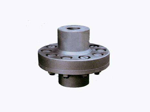
 Elastic sleeve pin coupling for pumpElastic sleeve pin coupling for pump: 1. Elastic...
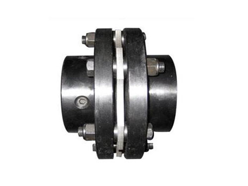 DJM type diaphragm couplingDiaphragm coupling forging materials need to be inspected...
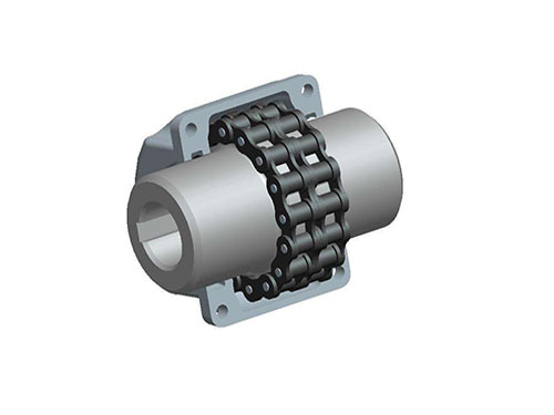 GL type roller chain couplingGL-type roller chain coupling AUTOCAD renderings...
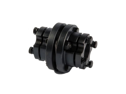 DJM expansion sleeve diaphragm couplingDJM expansion sleeve diaphragm coupling strength JZMJ type...
 ZL type elastic pin gear couplingZL type elastic pin gear coupling is the use of...
The selection of diaphragm coupling and the stress during rotation
The selection principle of diaphragm coupling has the following five points, let's take a look:
XNUMX. Diaphragm couplings are often used in servo systems. Diaphragms have good torque rigidity, but are slightly inferior to bellows couplings.
XNUMX. Adjust the model according to the shaft diameter: The initially selected coupling size of the bearing coupling, that is, the shaft hole diameter d and the shaft hole length L, should meet the requirements of the shaft diameter of the driving and driven ends, otherwise it must be adjusted according to the shaft diameter d The specifications of the coupling.
1.5. Diaphragm couplings are a bit like bellows couplings. In fact, couplings transmit torque in the same way.The diaphragm itself is very thin, so it is easy to bend when the relative displacement load is generated, so it can withstand up to XNUMX degrees of deviation, while generating a lower bearing load in the servo system.
XNUMX. Diaphragm coupling consists of at least one diaphragm and two shaft sleeves.The diaphragm is fastened to the shaft sleeve with a pin and generally does not loosen or cause backlash between the diaphragm and the shaft sleeve.Some manufacturers provide two diaphragms, and some provide three diaphragms, with one or two rigid elements in the middle, and the two sides are connected to the shaft sleeve.
XNUMX. Diaphragm couplings are especially delicate, and they are easily damaged if they are misused or not installed correctly during use.
For the stress analysis of the diaphragm coupling:
XNUMX. The bending stress caused by radial and angular displacement due to the actual installation error in the axial angle direction, the diaphragm is periodically bent and deformed along the axial direction, and it is the main factor that determines the fatigue life of the diaphragm. Find the size of the restoring torque.
XNUMX. When the diaphragm transmits torque, the torque is transmitted along the tangential direction of the bolt distribution circle through the active bolt and the diaphragm element to drive the driven bolt.Ignoring the slight relative movement between the diaphragms, it is considered that each diaphragm bears the torque evenly.When the elastic diaphragm coupling transmits torque, the diaphragm plane is stressed. The shaded circle represents the input of the active end, and the blank circle represents the output of the driven end.
0. Membrane surface stress (torque stress, suppose the transmission torque is T(N8m), the total number of pieces is m, for 4-hole bolts, from simplified conditions, T single piece = Tlm, each main bolt received The force is F=TlXNUMXmR.
Fourth, the bending stress caused by the axial displacement causes the diaphragm to bend and deform along the axial direction due to the installation error in the axial direction. The axial force can be calculated by the axial displacement.
XNUMX. Centrifugal stress Assuming that the bolt and the diaphragm are of the same material, the respective masses can be calculated. According to the position and the spiral angle, the centrifugal force can be calculated, and it acts on the total center of mass.
When the diaphragm coupling rotates, its angular deviation will produce alternating stress, which alternates once per rotation.The dynamic stress of the diaphragm will cause the fatigue damage of the diaphragm and the bolt, so the accurate calculation of the dynamic and static composite stress is the key to predicting the life of the diaphragm coupling and the work of the diaphragm coupling.The existing correlations are mostly limited to the analysis of the stress distribution of the diaphragm when it is subjected to a certain load, and the dynamic and static composite stress when the diaphragm is actually subjected to a complex load is rarely involved.The membrane segment between two adjacent bolt holes can be equivalent to a cantilever beam, and the material mechanics method is used to deduce that the connecting rod diaphragm coupling can bear torque, centrifugal load, axial offset and angular deviation. The calculation formula for the internal stress of the diaphragm is shifted, and a method for calculating the torsional stiffness of the diaphragm is proposed. It is a typical method to analyze the stress and stiffness of the diaphragm by using empirical formulas, but its shortcoming is that the stress concentration around the bolt hole cannot be considered. The influence of the effect leads to a large gap between the calculated stress and the actual stress.
The stability of the system tends to be affected by the misalignment of the bearings on both sides of the diaphragm coupling.Under the influence of misalignment, the smaller logarithmic decay rate of the system is reduced, and the instability speed drops.
The misalignment of the bearings on both sides of the coupling and the two ends of the system has different effects on the load distribution of the system support.The load distribution supported on both sides of the coupling increases with the increase of the misalignment, and decreases under the influence of the misalignment of the bearings at both ends of the system.The load distribution at the bearings at both ends of the system decreases with the increase of the misalignment at the supports on both sides of the coupling, and increases under the influence of the misalignment at its own.Due to the vibration isolation function of the diaphragm coupling, the misalignment at the support of the rotor system of one span has less effect on the dynamic and static characteristics of the rotor bearing of the other span.
The inherent characteristics of the system change under the effect of the misalignment, in which the corresponding value of the real part of the eigenvalue decreases, while the imaginary part increases, and the first few modes of the system no longer exhibit symmetrical or antisymmetric characteristics. The deformation of the rotor of one span is dominant, and the other span hardly deforms.
The unbalanced response of the rotor-bearing system of the diaphragm coupling.At first, the Gaussian elimination method was used to solve the forced vibration caused by the unbalanced amount of the system: the unbalanced response of each node was analyzed.Then, taking the multi-span rotor-bearing system with symmetrically arranged diaphragm couplings as the object, the effects of the stiffness of the diaphragm coupling and the misalignment of the rotor on the unbalanced response of the system are analyzed through numerical simulations; detailed analysis In the misalignment state, the unbalanced response of the system support varies with the speed. The main conclusions are as follows:
XNUMX. When the system passes the critical speed area, the misalignment of the rotor has a significant influence on the unbalanced response of the system, but at the working speed, this influence becomes smaller.
XNUMX. For a symmetrical rotor-bearing system, when the radial stiffness of the diaphragm coupling is equal to a certain value, its angular stiffness has a great influence on the unbalanced response of the system.In the case of the radial stiffness of the diaphragm coupling, the corner stiffness determines its vibration isolation effect.When k, is smaller, there is a significant vibration isolation function.With the increase of k, its vibration isolation effect gradually decreases.Analysis shows that the corner stiffness of the diaphragm coupling is an important factor affecting its vibration isolation effect.