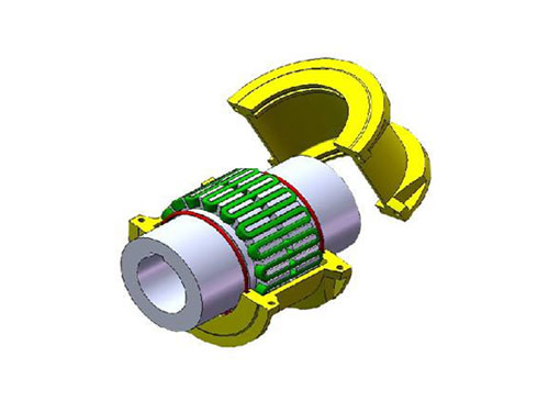
 JS type housing radial mounting type couplingSelection of JS type housing radial mounting type coupling...
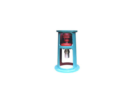 TB type HG5-251-69 standard rackThe standard frame of TB type HG5-251-69 is "glass-lined...
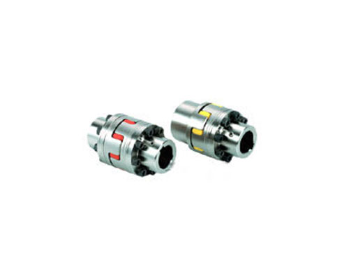 LMS type double flange type plum blossom elastic couplingLMS (formerly MLS) type-double-flange...
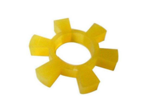 T type plum blossom hexagonal water pump counter wheel padT-shaped plum blossom hexagonal water pump for wheel pad products...
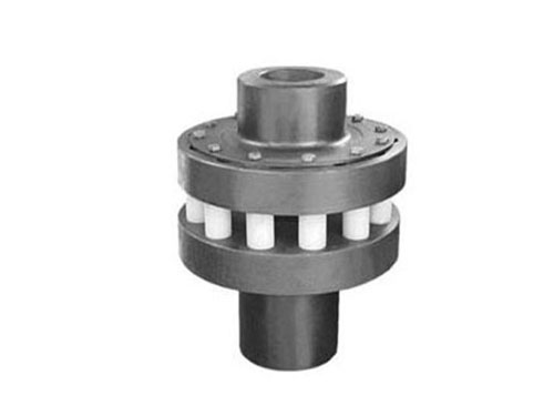 HL type elastic pin couplingThe elastic pin coupling uses a number of non...
The balance correction method and principle of diaphragm coupling
Diaphragm couplings were used in developed industrial applications in the 20s and 60s.After the reform and opening up, with the introduction of large-scale complete sets of industrial equipment, diaphragm couplings have gradually become known to the Chinese people. In the early 70s, some domestic institutions began to discuss the design and application of diaphragm couplings.After 20 years of development, its application performance has been developed from low-power, low-speed pump units to high-power, high-speed turbo compressor units.The domestic diaphragm coupling has basically replaced the product.At the same time, the diaphragm coupling is often used in the transformation of the old unit that originally used the gear coupling, and sometimes it has the effect of "resurrecting the dead".
In fact, these worries are now gone.Domestic mainstream companies generally start from basic research, master key technologies such as material selection, design calculation, processing technology, and dynamic balance, and have 20 years of engineering application experience.The elastic diaphragm coupling has also accumulated a lot of achievements in the field of high-speed and high-power.The key material is the metal diaphragm, which is generally made of austenitic stainless steel, and there is no difference between domestic materials; in terms of design calculations, finite element and optimization techniques have been commonly used; the stress distribution of a typical diaphragm is given by finite element analysis , The optimized diaphragm shape only retains the material that transmits the torque, and removes almost all the excess material. Such a diaphragm not only has reasonable stress distribution, but also has large flexibility, which can compensate for large misalignments, and The reaction force added to the connected device is small.
When the diaphragm coupling is used in process power equipment, the transmission torque should generally be determined according to the actual transmission power and actual working speed of the unit. Select the diaphragm coupling, so that the selected diaphragm coupling can not only meet the torque transmission requirements , And the structure is light and handy, the additional force and bending moment to the unit are also small.In order to pursue safety, some users increase the size of the coupling layer by layer when choosing the coupling. The couplings selected in this way are often too bulky and the use effect is not good.
The coupling is subjected to the combined action of steady-state load CAL torque, axial misalignment medium ring mouth alternating load CAL alternating torque, angular and radial misalignment during operation.Coupling manufacturers usually leave a fatigue coefficient when designing the product. The composite stress point of the key force component generally falls on the lower left of the revised Goodman curve (like a constant life curve), causing fatigue The coefficient is greater than 1.
When the coupling is selected, the manufacturer will multiply a reasonable working condition coefficient according to the severity of torque fluctuations under different working conditions. The actual working point will be farther away from the Goodman curve.The actual compound stress point position when choosing different working condition coefficients.According to the working condition coefficient of the diaphragm coupling, the working condition coefficient should not be less than 1.5. When it is really needed, the shafting matching requires the supply and demand parties to negotiate and reduce the working condition coefficient, but the value should not be less than 1.2.
The balance correction method and principle of diaphragm coupling
1. Due to various reasons, the center of mass or inertial principal axis of the diaphragm coupling does not coincide with the axis of rotation. During operation, the phenomenon of unbalanced centrifugal inertial force, centrifugal inertial couple force and dynamic deflection (vibration shape) will occur, which is called The unbalance phenomenon of the rotor, this unbalance phenomenon will inevitably cause the vibration of the shaft system, thereby affecting the normal operation and service life of the machine, so it is important to pay attention to it.
2. The degree of unbalance (unbalance U) is usually expressed by the product mr of the mass m of the rotor and the distance r from the center of mass to the axis of rotation of the rotor, which is called the product of mass diameter.It is also expressed by the product of mass diameter per unit mass, which is called the eccentricity e (not geometrically eccentric.) The product of mass diameter mr is a relative quantity related to the mass of the rotor, while the eccentricity e is a value that has nothing to do with the mass of the rotor.的量。 The amount.
3. The former is relatively intuitive and is often used for the balancing operation of a specific given rotor, while the latter is used to measure the pros and cons of the rotor balance or to check the balance accuracy. The balance grade standard of the coupling is evaluated by e.For a flexible rotor, use the mode eccentricity (the nth mode) en=Un/mn, and Un and mn are the nth mode and the first mode quality respectively.
4. In order to correct or minimize the unbalance of the coupling, select the appropriate balance level according to the needs, and after the product is manufactured and installed on the machine, on the balance (correction) plane designated by the coupling , By increasing or decreasing the appropriate quality method to achieve the balance level requirements.This process is called balance correction, or balance for short.