 FCL type elastic sleeve pin couplingThe characteristics of FCL type elastic sleeve pin coupling...
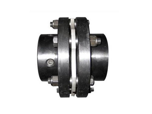 DJM type diaphragm couplingDiaphragm coupling forging materials need to be inspected...
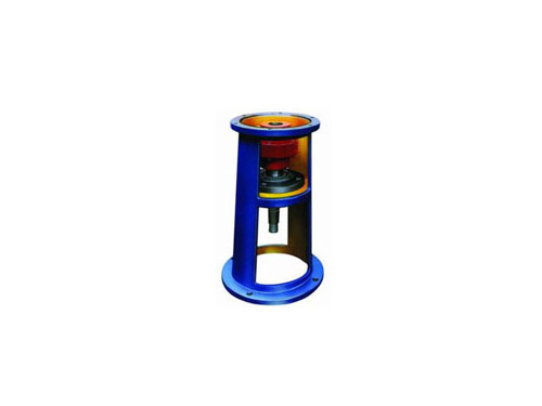 JB type HG5-251-79 standard frameThe selection of JB type HG5-251-79 standard frame, the original...
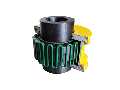 JSB type axial mounting couplingThe general material of J-type axial installation coupling...
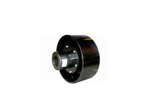 HLL type brake wheel elastic pin couplingHLL type brake wheel elastic pin coupling has...
Types of couplings and local structure of diaphragm elastic couplings
Couplings are also called couplings.A mechanical component used to connect the driving shaft and the driven shaft in different mechanisms to rotate together and transmit motion and torque.Sometimes it is also used to connect shafts and other parts (such as gears, pulleys, etc.).It is often composed of two halves, which are connected by keys or tight fits, respectively, and fastened to the ends of the two shafts, and then the two halves are connected in some way.The coupling can also compensate for the offset between the two shafts due to inaccurate manufacturing and installation, deformation or thermal expansion during work, etc. (including axial offset, radial offset, angular offset or comprehensive offset) ; And alleviate impact and absorb vibration.
The main types of couplings are diaphragm couplings and rigid couplings. There are many diaphragm couplings used in the market. Diaphragm couplings are divided into metal diaphragm couplings and non-metallic diaphragm couplings. Two kinds of devices.
The diaphragm coupling contains an elastic compound of pre-compressed rubber to provide additional strength and extend service life.The coupling can accommodate all types of deviations.The profile is made of aluminum alloy, which is both lightweight and eroded.Among them, the rubber component is mainly used for shock absorption, so that the power transmission is smooth and quiet, thereby protecting the driving force and driving the machine.
The installation is simple, because the rubber part is a split insert, it can be plug-in installation after the axis is aligned.
The diaphragm coupling uses a parallel or spiral groove system to adapt to various deviations and accurately transmit torque.Diaphragm couplings usually have good performance and price advantages. In many practical applications of stepping and servo systems, diaphragm couplings are the main product of choice.The one-piece design enables the diaphragm coupling to achieve the advantages of zero-clearance torque transmission and no maintenance.Diaphragm couplings mainly have the following two basic series: spiral groove type and parallel groove type.
Describe the partial structure and function of the diaphragm elastic coupling:
0.05. Mounting plate: The fit between the inner hole and the journal is generally designed as a "transition fit" or "interference fit". Therefore, the inner hole of the mounting plate and the outer diameter of the shaft should be carefully checked before installation to ensure that the surface is clean and free of burrs.For the correct installation of the mounting plate, a dial indicator can be used to detect the outer circle and end surface of the mounting plate. The runout of the outer circle and end surface should not be greater than 0.05mm. The dial indicator can be used to detect the outer circle and end surface of the mounting plate. The runout of the end face and the end face should not be greater than 250mm, and the end face runout is allowed to be 0.08mm under limited circumstances for the mounting plate with an outer diameter greater than XNUMXmm or a taper hole.
120. For a straight shaft: Put the key in the keyway on the shaft. The key end should not protrude or recess into the shaft end. It is better to be flush.Put the mounting plate in the oil tank and heat it at a temperature of 150~XNUMX℃. After heating and keeping warm, install it at the required position on the shaft according to the coupling installation drawing and pay attention to the position mark. The mounting plate and the shaft end should generally be flush.Partial heating is not allowed during heating to avoid deformation.
XNUMX. For tapered shaft: Install the key on the shaft according to the same requirements as the straight shaft key, then install the mounting plate on the shaft, push it tightly, and tighten it with a nut to make the mounting plate move axially to it. Fixed position.The distance from the initial position to the working position is also called the axial advance value. The axial advance value = hub diameter fit interference value, taper K.
Alignment is an important part of the installation. According to the type of machine and equipment and the alignment requirements, the runout value can be measured on the end face and outer circle of the coupling mounting plate with a dial indicator. This method can be regarded as an accurate method. But it's a little troublesome.Use two dial gauges to simultaneously measure the data on the outer circle of the coupling mounting plate. This method is good and fast. It does not need to consider the change of the shaft end, especially in the field, which can easily and quickly complete the measurement work.The ruler and inner caliper method are suitable for occasions with low requirements and low precision.If the unit needs (for example, the shaft head distance is long, or the centering accuracy is particularly high), the influence of the meter rod sag on the misalignment value should be included.The sagging amount of the benchmark can be measured in advance according to the following steps and recorded.Fix the watch frame according to the length L of the watch rod required for actual alignment, and then install the magnetic base on a rigid plate.Put the plate upright first, then put it upside down, and read the difference between the dial gauge readings and the misalignment data allowed during installation, namely axial, angular (bounce of the end face of the mounting plate), and radial (bounce of the outer circle of the mounting plate) ), the three-way misalignment data should be provided by various equipment manufacturers. When the coupling user has no requirements, it is recommended to use the data in the attached table or negotiate.
The diaphragm-type elastic coupling compensates for the relative displacement of the two shafts connected by the elastic deformation of the diaphragm. It is a high-performance flexible coupling with metal elastic elements. It does not require lubrication, has a compact structure, and has a long service life. The rotation gap is not affected by temperature and oil pollution, and has the characteristics of acid and alkali resistance. It is suitable for shaft transmission in high temperature and corrosive medium conditions. It is generally used for shaft transmission of various mechanical devices, such as water pumps (especially It is a high-power, chemical pump), fans, compressors, hydraulic machinery, petroleum machinery, printing machinery, textile machinery, chemical machinery, mining machinery, metallurgical machinery, naval high-speed power transmission system, after being dynamically balanced, it is applied to high-speed transmission shaft system Has become more common.