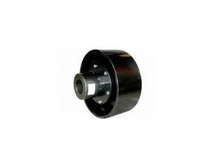
 HLL type brake wheel elastic pin couplingHLL type brake wheel elastic pin coupling has...
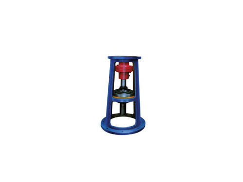 JXLD, JBLD model frame (new standard)The JXLD type of this rack series is suitable for...
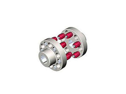 HL type elastic pin couplingThe elastic pin coupling (GB5014-85) is suitable for...
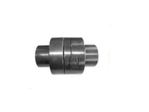 SL cross slider couplingCross slider coupling is also known as metal slider...
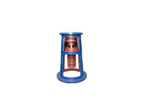 TJQ frameThe choice of TJQ type frame is basically...
The selection steps of the coupling and the maintenance specification of the diaphragm coupling
The couplings have been standardized or standardized.The designer's task is to choose, not design.The basic steps for selecting a coupling are as follows:
XNUMX. The working speed of the coupling and the centrifugal force caused by it.For the drive shaft, a coupling with good balance accuracy, such as a diaphragm coupling, should be used, rather than a slider coupling with eccentricity.
XNUMX. The sex and working environment of the coupling.Comparison of couplings usually made of metal elements that do not require lubrication; couplings that require lubrication are easily affected by the degree of lubrication and may pollute the environment.Couplings containing non-metallic components such as rubber are more sensitive to temperature, corrosive media and strong light, and are prone to aging.
XNUMX. Due to reasons such as manufacturing, installation, load deformation and temperature changes, it is difficult to maintain strict alignment of the two shafts after installation and adjustment.There are corresponding degrees of displacement in the x and Y directions and the deflection angle CI.When the radial displacement is large, the slider coupling can be selected, and the universal coupling can be selected for the connection of large angular displacement or intersecting two shafts.When the two shafts produce a large additional relative displacement during the working process, a flexible coupling should be used.
Fourth, the size and nature of the torque to be transmitted and the requirements for the function of buffering and damping.For example, for high-power and heavy-duty transmissions, gear couplings can be used; for transmissions that require severe impact loads or shaft torsional vibrations, tire couplings can be used.
When the diaphragm coupling leaves the factory, it is generally required to strictly implement the standard that the radial direction is less than or equal to 0.15mm, and the end face runout is less than or equal to 0.1mm.This is mainly considered from the service life of the coupling.
XNUMX. Bending stress caused by angular installation error (periodical profit).Due to the actual installation error in the axial angular direction, the diaphragm is periodically deformed along the axial direction, and it is the main factor that determines the fatigue life of the diaphragm.
4. Film stress caused by torque.The force generated by the torque on one side is evenly distributed on the four spaced bolt holes. On all 1/4 diaphragms, the force acts on the middle of one side of the middle bolt hole in the circumferential direction to fix the radial displacement and the axial direction. Displacement.
2. Centrifugal stress produced by centrifugal inertial force.High-speed mechanical centrifugal inertial force is important in the stress calculation of the structure. The centrifugal inertial force can be loaded according to the radial unit body force f=2rρ(60πn/0.15), and the direction is radially outward. In the formula, n is the speed and r is The radius, ρ is the density.Fix the radial displacement, circumferential displacement and axial displacement of the middle bolt hole, and there is no other load around it.Analyzed from the related formula (omitted), the magnitude of the additional stress is not only related to the angular displacement of the two shafts and the relative axial displacement of the two shafts, but also to the number of bolts of the coupling, the thickness of the diaphragm, and the distribution radius of the coupling bolts. Therefore, it is recommended that the specific calibration standards should be carried out according to the equipment design requirements, and the radial direction should be less than or equal to 0.1mm, and the end face runout should be less than or equal to XNUMXmm.
XNUMX. Bending stress caused by axial installation error.Due to the actual installation error in the axial direction, the diaphragm is installed along the axial direction and bends and deforms.The displacement is loaded in the axial direction of the middle bolt hole, and the radial displacement and the axial displacement are fixed.
Maintenance specifications of diaphragm couplings:
XNUMX. Especially in the machinery and equipment used in various hardware machinery, to prevent the machinery and equipment from appearing various problems in the whole process of this application, and can exceed a long period of use, everyone can be at ease The development and selection of applications.
XNUMX. Only then can the advantages be used to obtain better considerations, and it will also allow everyone to obtain better quality in the entire process of actual use.
XNUMX. The design of the diaphragm coupling is relatively simple, and it can fully exert a good practical effect in the whole process of application, and there is no need to apply lubricating fluid, so it can exceed the more convenient specification at the time of maintenance. .
Fourth, nature can consider the application regulations of various different manufacturing industries, and it is convenient to carry out inspections and inspections at ordinary times, and it is also convenient in the whole process of repair and maintenance.
XNUMX. The quality of the diaphragm coupling. The left and right means the detailed introduction to the multi-angle of the diaphragm coupling. I firmly believe that everyone should have a multi-angle understanding of the use of this type of coupling. As far as different types of couplings are concerned, it is suggested that everyone should make certain choices.
XNUMX. The diaphragm coupling is highly sensitive, has a smooth application effect, and has a high sensitivity. The more important thing is that it can have a good radial error working ability, so when the application is carried out, the machine equipment Have a good practical effect of stable maintenance.
XNUMX. It is proposed that everyone should be able to integrate their own actual requirements to carry out selection, so that nature can give full play to the relatively good application advantages, and can produce a relatively complete compensation work ability, which is suitable for various high-speed places.
XNUMX. The design of the diaphragm coupling is simple and easy to use. The diaphragm coupling produced by the coupling manufacturer can not only have a relatively stable structure, but also have good practical effects in the whole process of long-term operation. Let the bearing capacity exceed the better specifications.
Next:Nothing