Product Description
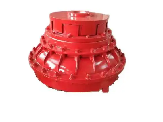
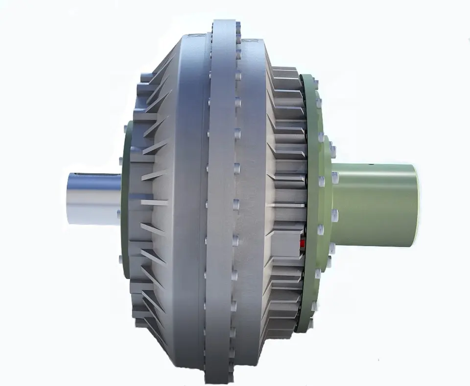
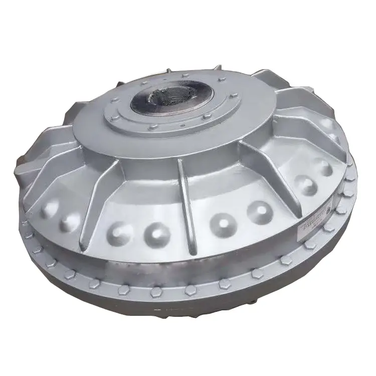
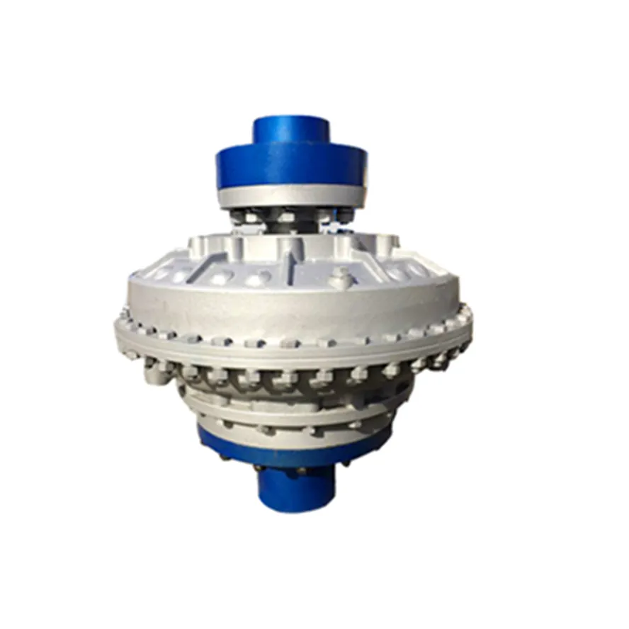
Clamped compressio Flexible Rubber Motor Quick Release Spline Fluid Shaft flange sleeve split threaded stainless steel Hydrodynamic custom rigid Coupling
Spline fluid shafts are used in a variety of applications, including:
- Hydraulic pumps and motors
- Gearboxes
- Compressors
- Turbines
- Machine tools
- Robots
- Material handling equipment
- Construction equipment
- Mining equipment
- Aerospace and defense applications
Spline fluid shafts are characterized by their ability to transmit high torque and power while minimizing vibration and noise. They are also relatively easy to manufacture and install, making them a cost-effective solution for a wide range of applications.
Here are some specific examples of how spline fluid shafts are used in different applications:
- In hydraulic pumps and motors, spline fluid shafts transmit the power from the motor to the pump. This allows the pump to operate at high speeds and pressures without the risk of damage.
- In gearboxes, spline fluid shafts transmit the power from the input shaft to the output shaft. This allows the gearbox to change the speed and direction of rotation of the output shaft.
- In compressors, spline fluid shafts transmit the power from the motor to the compressor. This allows the compressor to operate at high speeds and pressures without the risk of damage.
- In turbines, spline fluid shafts transmit the power from the rotating shaft to the generator. This allows the turbine to generate electricity at high speeds and pressures.
- In machine tools, spline fluid shafts transmit the power from the motor to the cutting tool. This allows the cutting tool to operate at high speeds and pressures without the risk of damage.
- In robots, spline fluid shafts transmit the power from the motor to the actuator. This allows the actuator to move the robot arm at high speeds and with precise control.
- In material handling equipment, spline fluid shafts transmit the power from the motor to the conveyor belt. This allows the conveyor belt to move materials at high speeds and with precise control.
- In construction equipment, spline fluid shafts transmit the power from the motor to the hydraulic cylinders. This allows the hydraulic cylinders to lift and move heavy objects at high speeds and with precise control.
- In mining equipment, spline fluid shafts transmit the power from the motor to the drill bits. This allows the drill bits to penetrate hard rock at high speeds and with precise control.
- In aerospace and defense applications, spline fluid shafts are used in a variety of components, including jet engines, helicopter rotors, and missile guidance systems.
Spline fluid shafts are a versatile and reliable component that can be used in a wide range of applications. They are characterized by their ability to transmit high torque and power while minimizing vibration and noise. Spline fluid shafts are also relatively easy to manufacture and install, making them a cost-effective solution for a wide range of applications.
/* January 22, 2571 19:08:37 */!function(){function s(e,r){var a,o={};try{e&&e.split(“,”).forEach(function(e,t){e&&(a=e.match(/(.*?):(.*)$/))&&1

Key Parameters in Designing a Fluid Coupling System
Designing a fluid coupling system requires careful consideration of various parameters to ensure optimal performance and efficiency. Here are the key parameters to take into account:
- Power Rating: Determine the power requirements of the connected equipment to select a fluid coupling with an appropriate power rating. Undersized couplings may lead to overheating and premature wear, while oversized couplings can result in energy losses.
- Input and Output Speeds: Consider the rotational speeds of the input and output shafts to ensure the fluid coupling can accommodate the desired speed range without slipping or exceeding its limitations.
- Torque Capacity: Calculate the maximum torque expected in the system and choose a fluid coupling with a torque capacity that exceeds this value to handle occasional overloads and prevent damage.
- Fluid Viscosity: The viscosity of the fluid inside the coupling affects its torque transmission capabilities. Select a fluid viscosity suitable for the application and operating conditions.
- Start-Up and Load Conditions: Analyze the start-up torque and load variations during operation. The fluid coupling should be capable of handling these conditions without excessive slip or stress on the drivetrain.
- Environmental Factors: Consider the ambient temperature, humidity, and potential exposure to contaminants. Ensure the fluid coupling’s materials and sealing mechanisms can withstand the environmental conditions.
- Size and Weight: Optimize the size and weight of the fluid coupling to minimize space requirements and facilitate installation and maintenance.
- Torsional Resonance: Evaluate torsional resonances in the system and select a fluid coupling with appropriate damping characteristics to mitigate vibrations.
- Overload Protection: Determine if overload protection features, such as slip or torque limiting, are necessary to safeguard the connected equipment from damage.
- Compatibility: Ensure the fluid coupling is compatible with the specific application, including the type of driven equipment, its mechanical characteristics, and any other interrelated components in the drivetrain.
- Operational Costs: Consider the long-term operational costs, maintenance requirements, and efficiency of the fluid coupling to optimize the overall lifecycle cost of the system.
- Safety Standards: Adhere to relevant safety standards and regulations in the design and installation of the fluid coupling system to ensure safe and reliable operation.
By carefully evaluating these parameters and selecting a fluid coupling that aligns with the specific requirements of the application, engineers can design a reliable and efficient fluid coupling system for various industrial and power transmission applications.

Cost Implications of Using Fluid Couplings in Comparison to Other Power Transmission Methods
The cost implications of using fluid couplings in power transmission depend on various factors, including the application requirements, the size of the system, and the operational conditions. While fluid couplings offer several advantages, they may have different cost considerations compared to other power transmission methods like mechanical clutches, VFDs (Variable Frequency Drives), and direct mechanical drives.
1. Initial Investment:
The initial cost of a fluid coupling can be higher than that of a mechanical clutch or a direct mechanical drive. Fluid couplings contain precision components, including the impeller and turbine, which can impact their initial purchase price.
2. Maintenance Costs:
Fluid couplings are generally considered to have lower maintenance costs compared to mechanical clutches. Mechanical clutches have wear and tear components that may require more frequent replacements, leading to higher maintenance expenses over time.
3. Energy Efficiency:
Fluid couplings are highly efficient in power transmission, especially during soft-start applications. Their ability to reduce shock loads and provide a smooth acceleration can result in energy savings and operational cost reductions.
4. Space and Weight:
Fluid couplings are usually more compact and lighter than some mechanical clutches, which can be advantageous in applications with space constraints or weight limitations.
5. Specific Application Considerations:
The suitability and cost-effectiveness of fluid couplings versus other power transmission methods can vary based on specific application requirements. For example, in soft-start applications, fluid couplings may be the preferred choice due to their ability to reduce mechanical stress and protect connected equipment.
6. Lifespan and Reliability:
While the initial cost of a fluid coupling might be higher, their longevity and reliability can lead to lower overall life cycle costs compared to other power transmission methods.
In conclusion, the cost implications of using fluid couplings in power transmission depend on the particular application and the total cost of ownership over the equipment’s lifespan. Although fluid couplings may have a higher initial investment, their long-term reliability, energy efficiency, and lower maintenance costs can make them a cost-effective choice in many industrial applications.

Fluid Couplings and Variable Speed Control
Fluid couplings are well-suited for certain applications that require variable speed control. While fluid couplings are primarily designed for smooth power transmission and torque multiplication, they can be used in combination with other devices to achieve variable speed control.
The primary method of achieving variable speed control with a fluid coupling is by using a hydraulic coupling or a hydraulic torque converter. A hydraulic coupling is essentially a fluid coupling with an additional chamber that allows for controlled fluid flow. By adjusting the fluid flow rate, the output speed can be varied, thus providing variable speed control.
Hydraulic torque converters are similar to fluid couplings but have an additional component called a stator. The stator redirects the fluid flow in a way that enhances torque multiplication at low speeds and improves efficiency at high speeds. By altering the stator’s position, the output speed can be varied, enabling variable speed control.
Variable speed control with fluid couplings is often used in applications such as industrial machinery, mining equipment, and certain types of vehicles. It allows for smooth and efficient speed adjustments without the need for mechanical gear changes, providing flexibility in various operating conditions.
However, it’s important to note that while fluid couplings can offer some degree of variable speed control, they are not as versatile as other speed control mechanisms like variable frequency drives (VFDs) or electronic controllers. Therefore, the selection of the appropriate speed control method depends on the specific requirements and characteristics of the application.


editor by CX 2024-02-27
China Best Sales Clamped Compression Flexible Rubber Motor Quick Release Spline Fluid Shaft Flange Sleeve Split Threaded Stainless Steel Hydrodynamic Custom Rigid Coupling
Product Description
Clamped Compression Flexible Rubber Motor Quick Release Spline Fluid Shaft Flange Sleeve Split Threaded Stainless Steel Hydrodynamic Custom Rigid Coupling
A custom rigid coupling is a mechanical component used to connect 2 rotating shafts in a machine or system. It is designed to transmit torque between the shafts while maintaining their alignment and minimizing any misalignment that may occur during operation.
Rigid couplings are typically made of a durable material such as steel or aluminum and are designed to be very stiff, allowing them to transmit torque with minimal deflection or deformation. They are often used in high-speed or high-torque applications where flexibility or misalignment of the shafts is not desirable.
A custom rigid coupling is designed to meet the specific requirements of a particular machine or system. This may involve customizing the diameter, length, and other dimensions of the coupling to fit the shafts and mounting points in the system. Custom rigid couplings may also include features such as keyways, set screws, or other attachment mechanisms to ensure a secure and reliable connection between the shafts.
Some common types of custom rigid couplings include:
– Clamp-style couplings use a split clamp design to secure the collar to the shafts. These are often used in applications where the shafts are difficult to access or where frequent disassembly is required.
– Set-screw couplings use set screws to secure the collar to the shafts. These are often used in low-torque applications where simplicity and ease of installation are essential.
– Flanged couplings use a flange on each end to connect the collar to the shafts. These are often used in applications where a high degree of precision and alignment is required.
Overall, a custom rigid coupling is an essential component in many types of machinery and systems, providing a reliable and efficient means of transmitting torque between 2 rotating shafts.
/* March 10, 2571 17:59:20 */!function(){function s(e,r){var a,o={};try{e&&e.split(“,”).forEach(function(e,t){e&&(a=e.match(/(.*?):(.*)$/))&&1

Handling Overloads and Stall Conditions in Fluid Couplings
A fluid coupling is designed to handle overloads and stall conditions in power transmission systems. When an overload or stall occurs, the fluid coupling utilizes its unique operating principle to protect the drivetrain and the connected machinery:
- Slip Feature: One of the key characteristics of a fluid coupling is its ability to slip at high torque loads. When an overload situation arises, the fluid coupling allows some relative motion between the input and output sides, known as slip. This slip absorbs the excess torque and prevents it from being transferred to the driven equipment, effectively protecting it from damage.
- Fluid Circulation: During normal operation, the fluid inside the coupling circulates smoothly between the impeller and turbine, transmitting torque with minimal losses. However, when an overload or stall condition occurs, the fluid circulation may become turbulent, generating heat in the process. This heat dissipation helps in absorbing and dissipating the excess energy, preventing the transmission system from experiencing sudden stress.
- Automatic Reconnection: After an overload or stall condition, once the excess torque is dissipated through slip and heat, the fluid coupling automatically reconnects the input and output sides, resuming the power transmission. This automatic reconnection ensures that the system returns to normal operation once the overload situation is resolved.
- Sturdy Construction: Fluid couplings are designed with robust and durable materials to withstand high torque and thermal stresses during overload conditions. The strong construction ensures that the fluid coupling remains reliable and operational even after multiple overload events.
Overall, a fluid coupling’s ability to handle overloads and stall conditions makes it a reliable and essential component in various industrial applications. By providing overload protection and slip characteristics, fluid couplings help prevent costly damage to equipment, increase operational safety, and contribute to the longevity of the entire power transmission system.

Fluid Couplings in High-Temperature Environments
Fluid couplings are versatile power transmission devices commonly used in various industrial applications. However, their suitability for high-temperature environments depends on several factors, including the design, materials, and the specific operating conditions.
Here are some key considerations regarding the use of fluid couplings in high-temperature environments:
- Fluid Type: The type of fluid used inside the coupling greatly influences its temperature capabilities. Some fluid couplings are designed to handle higher temperatures by using specially formulated high-temperature fluids that can withstand elevated heat levels without degradation.
- Materials: The materials used in the construction of the fluid coupling play a crucial role in determining its maximum temperature tolerance. High-quality materials with good heat resistance properties are required to ensure reliable performance in high-temperature conditions.
- Lubrication: Proper lubrication is essential to reduce friction and heat generation within the fluid coupling. In high-temperature environments, ensuring sufficient and appropriate lubrication is crucial to prevent excessive wear and potential damage.
- Cooling: Some fluid couplings come equipped with cooling systems, such as cooling fins or external cooling circuits, to dissipate excess heat generated during operation. These cooling mechanisms can enhance the coupling’s capacity to handle higher temperatures.
- Application Considerations: The specific application and load requirements must be taken into account. In some cases, high-temperature conditions may be intermittent or occasional, allowing the fluid coupling to cool down between cycles. However, continuous high-temperature operation may require a more robust and specialized fluid coupling.
It is important to consult with the fluid coupling manufacturer to understand the temperature limitations and performance capabilities of their products. Manufacturers can provide guidance on selecting the appropriate fluid coupling for specific high-temperature applications.
While fluid couplings can be suitable for moderate to high-temperature environments, it is essential to operate them within their specified temperature range to ensure optimal performance and longevity. Extreme temperatures beyond the coupling’s rated limits can lead to accelerated wear, reduced efficiency, and potential damage, ultimately affecting the reliability of the power transmission system.
In summary, fluid couplings can be used in high-temperature environments, provided that the coupling’s design, materials, and lubrication are suitable for the specific application and operating conditions. Regular maintenance and adherence to the manufacturer’s guidelines are essential to ensure reliable performance and durability in such environments.

Use of Fluid Couplings in Horizontal and Vertical Shaft Arrangements
Yes, fluid couplings can be used in both horizontal and vertical shaft arrangements, providing flexible power transmission solutions for various industrial applications.
1. Horizontal Shaft Arrangements:
In horizontal shaft arrangements, the fluid coupling is installed between the driving and driven shafts, which are positioned horizontally and parallel to each other. The fluid coupling allows torque to be transmitted smoothly from the driving shaft to the driven shaft, enabling the machinery or equipment to start up gradually without abrupt shocks or overloading. This feature is especially beneficial in applications where heavy loads need to be accelerated smoothly, such as conveyors, crushers, and pumps.
2. Vertical Shaft Arrangements:
In vertical shaft arrangements, the fluid coupling is used to connect the driving and driven shafts, which are positioned vertically and aligned on top of each other. The fluid coupling allows for torque transmission and controlled acceleration, just like in horizontal arrangements. Vertical shaft fluid couplings are commonly used in applications such as vertical conveyors, hoists, and elevators, where they provide smooth starting and stopping of the equipment, preventing sudden jolts and reducing stress on the machinery.
Fluid couplings offer versatility in power transmission and are adaptable to various shaft arrangements, making them suitable for a wide range of industrial setups. Whether the application involves horizontal or vertical shafts, fluid couplings play a crucial role in enhancing the performance, safety, and efficiency of power transmission systems.


editor by CX 2024-02-22