Product Description
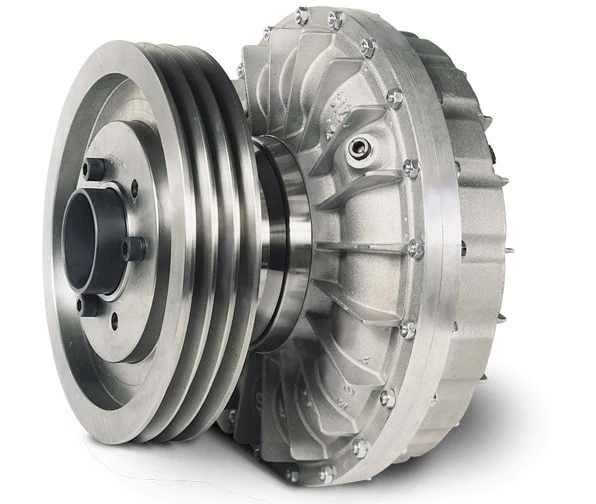
Diaphragm Coupling Shaft Coupling (JMI)
JM Series Diaphragm Coupling of flexible metal flexible coupling, which rely on the metal diaphragm to transmit torque from the main connection, motivation, has the advantages of elastic damping and no lubrication, no noise, is an ideal product for replacing the gear coupling and coupling current. It can compensate the axial, radial and angular deviation caused by the manufacturing error, installation error, bearing deformation and the change of temperature rise.
The main characteristics of JM Series Diaphragm Coupling:
1.Compensation 2 axis misalignment of the ability, and tooth type coupling can be much more than a double angle displacement, radial displacement of the small, flexible, allowing a certain axial, radial and angular displacement.
2. Obvious damping effect, no noise, no wear and tear.
3.High transmission efficiency, up to 99.86%. Especially suitable for medium and high speed high power transmission.
4.Adapt to high temperature (-80+300) and harsh environment, and can be in shock, vibration, safety and dynamic conditions.
5.Simple structure, light weight, small size, convenient assembly and disassembly. Without moving the machine can be disassembled (with intermediate type), no need of lubrication.
6.Accurately convey the rotational speed, the operation has not turned bad, can be used for the transmission of precision machinery.
JM series diaphragm flexible coupling is widely used in machinery and equipment industry, metallurgy, mines, petroleum, chemical, electric power, shipbuilding, lifting transport, textile, light industry, agricultural machinery, printing machinery and water pump, fan, etc. in the transmission of power machine.
|
||||||||||||||||||||||||||||||||||||||||||||||||||||||||||||||||||||||||||||||||||||||||||||||||||||||||||||||||||||||||||||||||||||||||||||||||||||||||||||||||||||||||||||||||||||||||||||||||||||||||||||||||||||||||||||||||||||||||||||||||||||||||||||||||||||||||||||||||||||||||||||||||||||||||||||||||||||||||||||||||||||||||||||||||||||||||||||||||||||||||||||||||||||||||
Detailed Photos
Company Profile
HangZhou CHINAMFG Machinery Manufacturing Co., Ltd. is a high-tech enterprise specializing in the design and manufacture of various types of coupling. There are 86 employees in our company, including 2 senior engineers and no fewer than 20 mechanical design and manufacture, heat treatment, welding, and other professionals.
Advanced and reasonable process, complete detection means. Our company actively introduces foreign advanced technology and equipment, on the basis of the condition, we make full use of the advantage and do more research and innovation. Strict to high quality and operate strictly in accordance with the ISO9000 quality certification system standard mode.
Our company supplies different kinds of products. High quality and reasonable price. We stick to the principle of “quality first, service first, continuous improvement and innovation to meet the customers” for the management and “zero defect, zero complaints” as the quality objective.
Our Services
1. Design Services
Our design team has experience in Cardan shafts relating to product design and development. If you have any needs for your new product or wish to make further improvements, we are here to offer our support.
2. Product Services
raw materials → Cutting → Forging →Rough machining →Shot blasting →Heat treatment →Testing →Fashioning →Cleaning→ Assembly→Packing→Shipping
3. Samples Procedure
We could develop the sample according to your requirement and amend the sample constantly to meet your need.
4. Research & Development
We usually research the new needs of the market and develop new models when there are new cars in the market.
5. Quality Control
Every step should be a particular test by Professional Staff according to the standard of ISO9001 and TS16949.
FAQ
Q 1: Are you a trading company or a manufacturer?
A: We are a professional manufacturer specializing in manufacturing
various series of couplings.
Q 2:Can you do OEM?
Yes, we can. We can do OEM & ODM for all customers with customized PDF or AI format artwork.
Q 3:How long is your delivery time?
Generally, it is 20-30 days if the goods are not in stock. It is according to quantity.
Q 4: Do you provide samples? Is it free or extra?
Yes, we could offer the sample but not for free. Actually, we have an excellent price principle, when you make the bulk order the cost of the sample will be deducted.
Q 5: How long is your warranty?
A: Our Warranty is 12 months under normal circumstances.
Q 6: What is the MOQ?
A: Usually our MOQ is 1pcs.
Q 7: Do you have inspection procedures for coupling?
A:100% self-inspection before packing.
Q 8: Can I have a visit to your factory before the order?
A: Sure, welcome to visit our factory.
Q 9: What’s your payment?
A:1) T/T.
♦Contact Us
Web: huadingcoupling
Add: No.11 HangZhou Road,Chengnan park,HangZhou City,ZheJiang Province,China
/* January 22, 2571 19:08:37 */!function(){function s(e,r){var a,o={};try{e&&e.split(“,”).forEach(function(e,t){e&&(a=e.match(/(.*?):(.*)$/))&&1

Contribution of Fluid Coupling to the Longevity of Connected Equipment
A fluid coupling plays a crucial role in enhancing the longevity and protecting the connected equipment by providing the following benefits:
- Shock Load Damping: When the equipment starts or stops, there can be sudden changes in torque, resulting in shock loads. The fluid coupling absorbs and dampens these shock loads, reducing stress and wear on the connected equipment.
- Torsional Vibration Damping: Torsional vibrations can occur during the operation of the connected equipment, which can be damaging over time. The fluid coupling acts as a torsional damper, reducing these vibrations and preventing potential fatigue failure in the equipment.
- Overload Protection: In case of sudden overloads or jamming of the connected equipment, the fluid coupling can slip and decouple the load, protecting both the equipment and the driving motor from excessive stress and damage.
- Smooth Startup: During startup, the fluid coupling allows a gradual increase in torque, enabling a smooth and controlled acceleration of the connected equipment. This eliminates sudden jerks and reduces mechanical stress during the startup phase.
- Load Distribution: The fluid coupling distributes the load evenly across the connected equipment, minimizing wear and tear on specific components and extending the overall lifespan of the machinery.
- Reduced Maintenance: By reducing shock loads and vibrations, the fluid coupling helps decrease the frequency of maintenance and repairs required for the connected equipment, resulting in cost savings and improved uptime.
- Energy Efficiency: The fluid coupling allows for efficient power transmission by reducing losses during startup and load changes. This, in turn, helps in lowering the overall energy consumption of the system and contributes to equipment longevity.
- Contamination Prevention: The fluid coupling encapsulates the driving and driven components, providing a barrier that helps prevent contaminants such as dust, dirt, and moisture from entering the equipment’s internal components. This protection can extend the life of bearings and other sensitive parts.
Overall, a fluid coupling acts as a protective intermediary between the driving motor and the connected equipment, enhancing the system’s reliability, efficiency, and longevity by mitigating the effects of shocks, vibrations, and overloads.

Safety Features in Modern Fluid Coupling Designs
Modern fluid coupling designs incorporate various safety features to ensure the reliable and secure operation of the equipment. Here are some of the key safety features commonly found in modern fluid couplings:
1. Overload Protection: One of the primary safety features in modern fluid couplings is overload protection. In the event of an abrupt increase in load or torque, the fluid coupling slips, absorbing the excess torque and preventing damage to the connected equipment. This feature safeguards against mechanical failures and protects the machinery.
2. Torque Limiting: Fluid couplings are designed with torque limiting capabilities, which allow them to control the maximum torque transmitted to the driven equipment. By setting the torque limit within a safe operating range, the fluid coupling prevents excessive stresses on the system, ensuring longevity and reliability.
3. Automatic Overheat Protection: Some fluid couplings are equipped with automatic overheat protection mechanisms. If the fluid coupling’s operating temperature exceeds a predefined threshold, the protection system disengages the coupling temporarily until the temperature returns to a safe level. This prevents damage due to overheating and enhances safety.
4. Backstop or Holdback Device: In certain applications where reverse rotation is a concern, fluid couplings may include a backstop or holdback device. This feature prevents the driven equipment from rotating in the opposite direction, enhancing safety during sudden stops or reversals.
5. Fail-Safe Operation: Many modern fluid couplings are designed to operate in a fail-safe manner. In the event of any malfunction or failure, the coupling defaults to a safe mode, allowing the equipment to continue operating at reduced capacity or gradually shut down, avoiding catastrophic failures.
6. Seal Protection: Proper sealing is crucial for fluid couplings, especially in harsh environments. Modern designs often include advanced seal protection features to prevent oil leakage and contamination, ensuring environmental safety and reducing maintenance requirements.
7. Low Noise and Vibration: Reduced noise and vibration levels in fluid couplings contribute to operator safety and comfort. The damping properties of the fluid coupling help minimize vibrations, creating a quieter and more stable working environment.
8. Emergency Stop Capability: Some fluid couplings may have emergency stop provisions to quickly disengage the coupling in critical situations. This feature allows for rapid shutdowns in emergencies, preventing accidents and protecting personnel.
9. Condition Monitoring: Advanced fluid coupling designs may include condition monitoring capabilities. This allows operators to monitor the coupling’s performance, temperature, and other parameters in real-time, facilitating predictive maintenance and avoiding unexpected failures.
Overall, the incorporation of these safety features in modern fluid coupling designs ensures the protection of machinery, operators, and the surrounding environment. These safety measures enhance the reliability, efficiency, and longevity of equipment, making fluid couplings a safe and valuable choice for power transmission in various industrial applications.

Use of Fluid Couplings in Horizontal and Vertical Shaft Arrangements
Yes, fluid couplings can be used in both horizontal and vertical shaft arrangements, providing flexible power transmission solutions for various industrial applications.
1. Horizontal Shaft Arrangements:
In horizontal shaft arrangements, the fluid coupling is installed between the driving and driven shafts, which are positioned horizontally and parallel to each other. The fluid coupling allows torque to be transmitted smoothly from the driving shaft to the driven shaft, enabling the machinery or equipment to start up gradually without abrupt shocks or overloading. This feature is especially beneficial in applications where heavy loads need to be accelerated smoothly, such as conveyors, crushers, and pumps.
2. Vertical Shaft Arrangements:
In vertical shaft arrangements, the fluid coupling is used to connect the driving and driven shafts, which are positioned vertically and aligned on top of each other. The fluid coupling allows for torque transmission and controlled acceleration, just like in horizontal arrangements. Vertical shaft fluid couplings are commonly used in applications such as vertical conveyors, hoists, and elevators, where they provide smooth starting and stopping of the equipment, preventing sudden jolts and reducing stress on the machinery.
Fluid couplings offer versatility in power transmission and are adaptable to various shaft arrangements, making them suitable for a wide range of industrial setups. Whether the application involves horizontal or vertical shafts, fluid couplings play a crucial role in enhancing the performance, safety, and efficiency of power transmission systems.


editor by CX 2024-05-15
China manufacturer Newest Sliver Rigid Fluid Diaphragm Coupling
Product Description
Diaphragm Coupling Shaft Coupling (JMI)
JM Series Diaphragm Coupling of flexible metal flexible coupling, which rely on the metal diaphragm to transmit torque from the main connection, motivation, has the advantages of elastic damping and no lubrication, no noise, is an ideal product for replacing the gear coupling and coupling current. It can compensate the axial, radial and angular deviation caused by the manufacturing error, installation error, bearing deformation and the change of temperature rise.
The main characteristics of JM Series Diaphragm Coupling:
1.Compensation 2 axis misalignment of the ability, and tooth type coupling can be much more than a double angle displacement, radial displacement of the small, flexible, allowing a certain axial, radial and angular displacement.
2. Obvious damping effect, no noise, no wear and tear.
3.High transmission efficiency, up to 99.86%. Especially suitable for medium and high speed high power transmission.
4.Adapt to high temperature (-80+300) and harsh environment, and can be in shock, vibration, safety and dynamic conditions.
5.Simple structure, light weight, small size, convenient assembly and disassembly. Without moving the machine can be disassembled (with intermediate type), no need of lubrication.
6.Accurately convey the rotational speed, the operation has not turned bad, can be used for the transmission of precision machinery.
JM series diaphragm flexible coupling is widely used in machinery and equipment industry, metallurgy, mines, petroleum, chemical, electric power, shipbuilding, lifting transport, textile, light industry, agricultural machinery, printing machinery and water pump, fan, etc. in the transmission of power machine.
|
||||||||||||||||||||||||||||||||||||||||||||||||||||||||||||||||||||||||||||||||||||||||||||||||||||||||||||||||||||||||||||||||||||||||||||||||||||||||||||||||||||||||||||||||||||||||||||||||||||||||||||||||||||||||||||||||||||||||||||||||||||||||||||||||||||||||||||||||||||||||||||||||||||||||||||||||||||||||||||||||||||||||||||||||||||||||||||||||||||||||||||||||||||||||
Detailed Photos
Company Profile
HangZhou CHINAMFG Machinery Manufacturing Co., Ltd. is a high-tech enterprise specializing in the design and manufacture of various types of coupling. There are 86 employees in our company, including 2 senior engineers and no fewer than 20 mechanical design and manufacture, heat treatment, welding, and other professionals.
Advanced and reasonable process, complete detection means. Our company actively introduces foreign advanced technology and equipment, on the basis of the condition, we make full use of the advantage and do more research and innovation. Strict to high quality and operate strictly in accordance with the ISO9000 quality certification system standard mode.
Our company supplies different kinds of products. High quality and reasonable price. We stick to the principle of “quality first, service first, continuous improvement and innovation to meet the customers” for the management and “zero defect, zero complaints” as the quality objective.
Our Services
1. Design Services
Our design team has experience in Cardan shafts relating to product design and development. If you have any needs for your new product or wish to make further improvements, we are here to offer our support.
2. Product Services
raw materials → Cutting → Forging →Rough machining →Shot blasting →Heat treatment →Testing →Fashioning →Cleaning→ Assembly→Packing→Shipping
3. Samples Procedure
We could develop the sample according to your requirement and amend the sample constantly to meet your need.
4. Research & Development
We usually research the new needs of the market and develop new models when there are new cars in the market.
5. Quality Control
Every step should be a particular test by Professional Staff according to the standard of ISO9001 and TS16949.
FAQ
Q 1: Are you a trading company or a manufacturer?
A: We are a professional manufacturer specializing in manufacturing
various series of couplings.
Q 2:Can you do OEM?
Yes, we can. We can do OEM & ODM for all customers with customized PDF or AI format artwork.
Q 3:How long is your delivery time?
Generally, it is 20-30 days if the goods are not in stock. It is according to quantity.
Q 4: Do you provide samples? Is it free or extra?
Yes, we could offer the sample but not for free. Actually, we have an excellent price principle, when you make the bulk order the cost of the sample will be deducted.
Q 5: How long is your warranty?
A: Our Warranty is 12 months under normal circumstances.
Q 6: What is the MOQ?
A: Usually our MOQ is 1pcs.
Q 7: Do you have inspection procedures for coupling?
A:100% self-inspection before packing.
Q 8: Can I have a visit to your factory before the order?
A: Sure, welcome to visit our factory.
Q 9: What’s your payment?
A:1) T/T.
♦Contact Us
Web: huadingcoupling
Add: No.11 HangZhou Road,Chengnan park,HangZhou City,ZheJiang Province,China
/* January 22, 2571 19:08:37 */!function(){function s(e,r){var a,o={};try{e&&e.split(“,”).forEach(function(e,t){e&&(a=e.match(/(.*?):(.*)$/))&&1

Handling Overloads and Stall Conditions in Fluid Couplings
A fluid coupling is designed to handle overloads and stall conditions in power transmission systems. When an overload or stall occurs, the fluid coupling utilizes its unique operating principle to protect the drivetrain and the connected machinery:
- Slip Feature: One of the key characteristics of a fluid coupling is its ability to slip at high torque loads. When an overload situation arises, the fluid coupling allows some relative motion between the input and output sides, known as slip. This slip absorbs the excess torque and prevents it from being transferred to the driven equipment, effectively protecting it from damage.
- Fluid Circulation: During normal operation, the fluid inside the coupling circulates smoothly between the impeller and turbine, transmitting torque with minimal losses. However, when an overload or stall condition occurs, the fluid circulation may become turbulent, generating heat in the process. This heat dissipation helps in absorbing and dissipating the excess energy, preventing the transmission system from experiencing sudden stress.
- Automatic Reconnection: After an overload or stall condition, once the excess torque is dissipated through slip and heat, the fluid coupling automatically reconnects the input and output sides, resuming the power transmission. This automatic reconnection ensures that the system returns to normal operation once the overload situation is resolved.
- Sturdy Construction: Fluid couplings are designed with robust and durable materials to withstand high torque and thermal stresses during overload conditions. The strong construction ensures that the fluid coupling remains reliable and operational even after multiple overload events.
Overall, a fluid coupling’s ability to handle overloads and stall conditions makes it a reliable and essential component in various industrial applications. By providing overload protection and slip characteristics, fluid couplings help prevent costly damage to equipment, increase operational safety, and contribute to the longevity of the entire power transmission system.
Temperature Limitations of Fluid Couplings
Fluid couplings, like any mechanical component, have temperature limitations that must be considered to ensure their proper and safe operation. The temperature limitations of fluid couplings are influenced by the type of fluid used inside the coupling, the ambient operating conditions, and the specific design and construction of the coupling.
The primary concern regarding temperature is the heat generated during the operation of the fluid coupling. The heat is a result of friction and fluid shear within the coupling as it transmits power between the input and output shafts. Excessive heat generation can lead to the degradation of the fluid, affecting the performance and longevity of the coupling.
As a general guideline, most fluid couplings are designed to operate within a temperature range of -30°C to 80°C (-22°F to 176°F). However, the actual temperature limitations may vary depending on the manufacturer and the application requirements. For specific industrial applications where high-temperature environments are common, fluid couplings with higher temperature tolerances may be available.
It is crucial to consider the operating environment and the power demands of the machinery when selecting a fluid coupling. In applications with extreme temperatures, additional cooling mechanisms such as external cooling fins or cooling water circulation may be employed to maintain the fluid coupling within its safe operating temperature range.
Exceeding the recommended temperature limits can lead to premature wear, reduced efficiency, and even mechanical failure of the fluid coupling. Regular monitoring of the operating temperature and following the manufacturer’s guidelines for maintenance and fluid replacement can help ensure the longevity and reliability of the fluid coupling.
Always consult with the manufacturer or a qualified engineer to determine the specific temperature limitations and suitability of the fluid coupling for your particular application.
Fluid Couplings and Variable Speed Control
Fluid couplings are well-suited for certain applications that require variable speed control. While fluid couplings are primarily designed for smooth power transmission and torque multiplication, they can be used in combination with other devices to achieve variable speed control.
The primary method of achieving variable speed control with a fluid coupling is by using a hydraulic coupling or a hydraulic torque converter. A hydraulic coupling is essentially a fluid coupling with an additional chamber that allows for controlled fluid flow. By adjusting the fluid flow rate, the output speed can be varied, thus providing variable speed control.
Hydraulic torque converters are similar to fluid couplings but have an additional component called a stator. The stator redirects the fluid flow in a way that enhances torque multiplication at low speeds and improves efficiency at high speeds. By altering the stator’s position, the output speed can be varied, enabling variable speed control.
Variable speed control with fluid couplings is often used in applications such as industrial machinery, mining equipment, and certain types of vehicles. It allows for smooth and efficient speed adjustments without the need for mechanical gear changes, providing flexibility in various operating conditions.
However, it’s important to note that while fluid couplings can offer some degree of variable speed control, they are not as versatile as other speed control mechanisms like variable frequency drives (VFDs) or electronic controllers. Therefore, the selection of the appropriate speed control method depends on the specific requirements and characteristics of the application.
editor by CX 2024-04-22
China wholesaler Newest Sliver Rigid Fluid Diaphragm Coupling
Product Description
Diaphragm Coupling Shaft Coupling (JMI)
JM Series Diaphragm Coupling of flexible metal flexible coupling, which rely on the metal diaphragm to transmit torque from the main connection, motivation, has the advantages of elastic damping and no lubrication, no noise, is an ideal product for replacing the gear coupling and coupling current. It can compensate the axial, radial and angular deviation caused by the manufacturing error, installation error, bearing deformation and the change of temperature rise.
The main characteristics of JM Series Diaphragm Coupling:
1.Compensation 2 axis misalignment of the ability, and tooth type coupling can be much more than a double angle displacement, radial displacement of the small, flexible, allowing a certain axial, radial and angular displacement.
2. Obvious damping effect, no noise, no wear and tear.
3.High transmission efficiency, up to 99.86%. Especially suitable for medium and high speed high power transmission.
4.Adapt to high temperature (-80+300) and harsh environment, and can be in shock, vibration, safety and dynamic conditions.
5.Simple structure, light weight, small size, convenient assembly and disassembly. Without moving the machine can be disassembled (with intermediate type), no need of lubrication.
6.Accurately convey the rotational speed, the operation has not turned bad, can be used for the transmission of precision machinery.
JM series diaphragm flexible coupling is widely used in machinery and equipment industry, metallurgy, mines, petroleum, chemical, electric power, shipbuilding, lifting transport, textile, light industry, agricultural machinery, printing machinery and water pump, fan, etc. in the transmission of power machine.
|
||||||||||||||||||||||||||||||||||||||||||||||||||||||||||||||||||||||||||||||||||||||||||||||||||||||||||||||||||||||||||||||||||||||||||||||||||||||||||||||||||||||||||||||||||||||||||||||||||||||||||||||||||||||||||||||||||||||||||||||||||||||||||||||||||||||||||||||||||||||||||||||||||||||||||||||||||||||||||||||||||||||||||||||||||||||||||||||||||||||||||||||||||||||||
Detailed Photos
Company Profile
HangZhou CHINAMFG Machinery Manufacturing Co., Ltd. is a high-tech enterprise specializing in the design and manufacture of various types of coupling. There are 86 employees in our company, including 2 senior engineers and no fewer than 20 mechanical design and manufacture, heat treatment, welding, and other professionals.
Advanced and reasonable process, complete detection means. Our company actively introduces foreign advanced technology and equipment, on the basis of the condition, we make full use of the advantage and do more research and innovation. Strict to high quality and operate strictly in accordance with the ISO9000 quality certification system standard mode.
Our company supplies different kinds of products. High quality and reasonable price. We stick to the principle of “quality first, service first, continuous improvement and innovation to meet the customers” for the management and “zero defect, zero complaints” as the quality objective.
Our Services
1. Design Services
Our design team has experience in Cardan shafts relating to product design and development. If you have any needs for your new product or wish to make further improvements, we are here to offer our support.
2. Product Services
raw materials → Cutting → Forging →Rough machining →Shot blasting →Heat treatment →Testing →Fashioning →Cleaning→ Assembly→Packing→Shipping
3. Samples Procedure
We could develop the sample according to your requirement and amend the sample constantly to meet your need.
4. Research & Development
We usually research the new needs of the market and develop new models when there are new cars in the market.
5. Quality Control
Every step should be a particular test by Professional Staff according to the standard of ISO9001 and TS16949.
FAQ
Q 1: Are you a trading company or a manufacturer?
A: We are a professional manufacturer specializing in manufacturing
various series of couplings.
Q 2:Can you do OEM?
Yes, we can. We can do OEM & ODM for all customers with customized PDF or AI format artwork.
Q 3:How long is your delivery time?
Generally, it is 20-30 days if the goods are not in stock. It is according to quantity.
Q 4: Do you provide samples? Is it free or extra?
Yes, we could offer the sample but not for free. Actually, we have an excellent price principle, when you make the bulk order the cost of the sample will be deducted.
Q 5: How long is your warranty?
A: Our Warranty is 12 months under normal circumstances.
Q 6: What is the MOQ?
A: Usually our MOQ is 1pcs.
Q 7: Do you have inspection procedures for coupling?
A:100% self-inspection before packing.
Q 8: Can I have a visit to your factory before the order?
A: Sure, welcome to visit our factory.
Q 9: What’s your payment?
A:1) T/T.
♦Contact Us
Web: huadingcoupling
Add: No.11 HangZhou Road,Chengnan park,HangZhou City,ZheJiang Province,China
/* January 22, 2571 19:08:37 */!function(){function s(e,r){var a,o={};try{e&&e.split(“,”).forEach(function(e,t){e&&(a=e.match(/(.*?):(.*)$/))&&1

Factors to Consider when Choosing between a Fluid Coupling and a VFD (Variable Frequency Drive)
When selecting between a fluid coupling and a VFD for a power transmission application, several factors should be taken into account:
- Speed Control Requirements: Consider whether variable speed control is essential for your application. VFDs are excellent for applications that require precise and flexible speed control, while fluid couplings typically offer limited speed control capabilities.
- Energy Efficiency: Evaluate the energy efficiency requirements of your system. VFDs can offer higher energy efficiency by allowing the motor to run at optimal speeds, whereas fluid couplings introduce some energy losses due to slip.
- Starting Torque: Examine the starting torque requirements of the driven load. Fluid couplings can provide high starting torque and smooth acceleration, which may be advantageous for applications with high inertia loads.
- Overload Protection: Consider the need for overload protection. Fluid couplings inherently provide some protection against shock loads by allowing slip, while VFDs may require additional protective mechanisms.
- Maintenance and Service: Evaluate the maintenance and service requirements of both systems. Fluid couplings are generally simpler and require less maintenance compared to VFDs, which involve electronic components.
- Cost: Compare the initial and long-term costs of both options. VFDs often have higher upfront costs but can provide significant energy savings in the long run, while fluid couplings may have lower initial costs but could lead to higher energy consumption.
Ultimately, the choice between a fluid coupling and a VFD depends on the specific needs of your application. Each option has its advantages and limitations, and a thorough analysis of the operating conditions and performance requirements will help determine the most suitable solution for your system.

Fluid Couplings in Pumps and Compressors
Yes, fluid couplings can be effectively used in pumps and compressors to optimize their operation and improve overall efficiency. Here’s how fluid couplings are beneficial in these applications:
1. Smooth Starting: Fluid couplings provide a soft-start capability, which is particularly advantageous for pumps and compressors. During startup, the fluid coupling allows the pump or compressor to gradually reach the desired operating speed, reducing mechanical stress on the equipment and preventing sudden torque spikes.
2. Overload Protection: Pumps and compressors may experience sudden changes in load due to variations in fluid demand or system pressure. A fluid coupling acts as a torque limiter and protects the connected equipment from damage during such overload conditions. It slips and absorbs excess torque, preventing mechanical failures and downtime.
3. Torque Control: Fluid couplings enable precise control over the torque transmitted to the pump or compressor. This feature allows operators to adjust the output speed and torque to match the specific requirements of the application, ensuring optimal performance and energy efficiency.
4. Vibration Damping: The inherent damping properties of fluid couplings help in reducing vibrations in pump and compressor systems. This not only extends the life of the mechanical components but also enhances the reliability of the entire system.
5. Energy Efficiency: By eliminating the need for direct mechanical connections and providing smooth acceleration, fluid couplings contribute to energy savings in pumps and compressors. The reduction in shock loads and vibrations leads to lower energy consumption and improved overall efficiency.
6. Heat Dissipation: Continuous operations in pumps and compressors can generate heat, potentially affecting the equipment’s performance. Fluid couplings have the ability to absorb and dissipate heat, maintaining proper operating temperatures and ensuring consistent performance.
7. System Protection: In addition to overload protection, fluid couplings also protect pumps and compressors from torque fluctuations, which can occur during transient conditions. This protection prevents mechanical damage and enhances the longevity of the equipment.
Overall, fluid couplings offer several advantages in pump and compressor applications, including smooth starting, overload protection, torque control, vibration damping, energy efficiency, heat dissipation, and system protection. These benefits make fluid couplings a valuable component in optimizing the performance and reliability of pumps and compressors in various industrial settings.
Applications of Fluid Couplings in Industrial Machinery
Fluid couplings are widely used in various industrial machinery and equipment due to their unique characteristics and benefits. Some common applications include:
- Conveyors: Fluid couplings are used in conveyor systems to provide smooth start-ups and overload protection. They help in preventing damage to the conveyor belts and equipment during sudden starts and stops.
- Pumps: Fluid couplings are employed in pumps to control the acceleration and deceleration of the pump impeller. This ensures a gradual and controlled flow of fluids, reducing water hammer and pressure surges.
- Fans: Industrial fans often use fluid couplings to regulate fan speed and avoid abrupt changes in airflow, which can cause mechanical stress and system instability.
- Mining Equipment: Fluid couplings are used in mining machinery, such as crushers and conveyors, to protect the drivetrain from shock loads and to enhance equipment reliability.
- Marine Propulsion Systems: In marine applications, fluid couplings are used in propulsion systems to provide smooth engagement of the propeller, protecting the engine and transmission.
- Power Plants: Fluid couplings are utilized in power plants for boiler feed pumps, induced draft fans, and other equipment to achieve smooth operation and prevent sudden stress on mechanical components.
- Steel Industry: In steel mills, fluid couplings are employed in various equipment, including rolling mills and continuous casting machines, to protect the machinery and enhance productivity.
- Automotive: Fluid couplings are used in automatic transmissions to smoothly transmit power from the engine to the wheels, allowing smooth gear changes and preventing driveline shock.
- Wood Processing: In wood processing equipment, such as chippers and saws, fluid couplings are used to protect the equipment from shock loads and to achieve efficient power transmission.
Overall, fluid couplings play a crucial role in a wide range of industrial machinery applications, providing enhanced protection, smoother operation, and increased equipment longevity.
editor by CX 2024-04-15
China OEM Newest Sliver Rigid Fluid Diaphragm Coupling
Product Description
Diaphragm Coupling Shaft Coupling (JMI)
JM Series Diaphragm Coupling of flexible metal flexible coupling, which rely on the metal diaphragm to transmit torque from the main connection, motivation, has the advantages of elastic damping and no lubrication, no noise, is an ideal product for replacing the gear coupling and coupling current. It can compensate the axial, radial and angular deviation caused by the manufacturing error, installation error, bearing deformation and the change of temperature rise.
The main characteristics of JM Series Diaphragm Coupling:
1.Compensation 2 axis misalignment of the ability, and tooth type coupling can be much more than a double angle displacement, radial displacement of the small, flexible, allowing a certain axial, radial and angular displacement.
2. Obvious damping effect, no noise, no wear and tear.
3.High transmission efficiency, up to 99.86%. Especially suitable for medium and high speed high power transmission.
4.Adapt to high temperature (-80+300) and harsh environment, and can be in shock, vibration, safety and dynamic conditions.
5.Simple structure, light weight, small size, convenient assembly and disassembly. Without moving the machine can be disassembled (with intermediate type), no need of lubrication.
6.Accurately convey the rotational speed, the operation has not turned bad, can be used for the transmission of precision machinery.
JM series diaphragm flexible coupling is widely used in machinery and equipment industry, metallurgy, mines, petroleum, chemical, electric power, shipbuilding, lifting transport, textile, light industry, agricultural machinery, printing machinery and water pump, fan, etc. in the transmission of power machine.
|
||||||||||||||||||||||||||||||||||||||||||||||||||||||||||||||||||||||||||||||||||||||||||||||||||||||||||||||||||||||||||||||||||||||||||||||||||||||||||||||||||||||||||||||||||||||||||||||||||||||||||||||||||||||||||||||||||||||||||||||||||||||||||||||||||||||||||||||||||||||||||||||||||||||||||||||||||||||||||||||||||||||||||||||||||||||||||||||||||||||||||||||||||||||||
Detailed Photos
Company Profile
HangZhou CHINAMFG Machinery Manufacturing Co., Ltd. is a high-tech enterprise specializing in the design and manufacture of various types of coupling. There are 86 employees in our company, including 2 senior engineers and no fewer than 20 mechanical design and manufacture, heat treatment, welding, and other professionals.
Advanced and reasonable process, complete detection means. Our company actively introduces foreign advanced technology and equipment, on the basis of the condition, we make full use of the advantage and do more research and innovation. Strict to high quality and operate strictly in accordance with the ISO9000 quality certification system standard mode.
Our company supplies different kinds of products. High quality and reasonable price. We stick to the principle of “quality first, service first, continuous improvement and innovation to meet the customers” for the management and “zero defect, zero complaints” as the quality objective.
Our Services
1. Design Services
Our design team has experience in Cardan shafts relating to product design and development. If you have any needs for your new product or wish to make further improvements, we are here to offer our support.
2. Product Services
raw materials → Cutting → Forging →Rough machining →Shot blasting →Heat treatment →Testing →Fashioning →Cleaning→ Assembly→Packing→Shipping
3. Samples Procedure
We could develop the sample according to your requirement and amend the sample constantly to meet your need.
4. Research & Development
We usually research the new needs of the market and develop new models when there are new cars in the market.
5. Quality Control
Every step should be a particular test by Professional Staff according to the standard of ISO9001 and TS16949.
FAQ
Q 1: Are you a trading company or a manufacturer?
A: We are a professional manufacturer specializing in manufacturing
various series of couplings.
Q 2:Can you do OEM?
Yes, we can. We can do OEM & ODM for all customers with customized PDF or AI format artwork.
Q 3:How long is your delivery time?
Generally, it is 20-30 days if the goods are not in stock. It is according to quantity.
Q 4: Do you provide samples? Is it free or extra?
Yes, we could offer the sample but not for free. Actually, we have an excellent price principle, when you make the bulk order the cost of the sample will be deducted.
Q 5: How long is your warranty?
A: Our Warranty is 12 months under normal circumstances.
Q 6: What is the MOQ?
A: Usually our MOQ is 1pcs.
Q 7: Do you have inspection procedures for coupling?
A:100% self-inspection before packing.
Q 8: Can I have a visit to your factory before the order?
A: Sure, welcome to visit our factory.
Q 9: What’s your payment?
A:1) T/T.
♦Contact Us
Web: huadingcoupling
Add: No.11 HangZhou Road,Chengnan park,HangZhou City,ZheJiang Province,China
/* January 22, 2571 19:08:37 */!function(){function s(e,r){var a,o={};try{e&&e.split(“,”).forEach(function(e,t){e&&(a=e.match(/(.*?):(.*)$/))&&1
Handling Overloads and Stall Conditions in Fluid Couplings
A fluid coupling is designed to handle overloads and stall conditions in power transmission systems. When an overload or stall occurs, the fluid coupling utilizes its unique operating principle to protect the drivetrain and the connected machinery:
- Slip Feature: One of the key characteristics of a fluid coupling is its ability to slip at high torque loads. When an overload situation arises, the fluid coupling allows some relative motion between the input and output sides, known as slip. This slip absorbs the excess torque and prevents it from being transferred to the driven equipment, effectively protecting it from damage.
- Fluid Circulation: During normal operation, the fluid inside the coupling circulates smoothly between the impeller and turbine, transmitting torque with minimal losses. However, when an overload or stall condition occurs, the fluid circulation may become turbulent, generating heat in the process. This heat dissipation helps in absorbing and dissipating the excess energy, preventing the transmission system from experiencing sudden stress.
- Automatic Reconnection: After an overload or stall condition, once the excess torque is dissipated through slip and heat, the fluid coupling automatically reconnects the input and output sides, resuming the power transmission. This automatic reconnection ensures that the system returns to normal operation once the overload situation is resolved.
- Sturdy Construction: Fluid couplings are designed with robust and durable materials to withstand high torque and thermal stresses during overload conditions. The strong construction ensures that the fluid coupling remains reliable and operational even after multiple overload events.
Overall, a fluid coupling’s ability to handle overloads and stall conditions makes it a reliable and essential component in various industrial applications. By providing overload protection and slip characteristics, fluid couplings help prevent costly damage to equipment, increase operational safety, and contribute to the longevity of the entire power transmission system.

Fluid Couplings for Soft-Start Applications in Conveyor Systems
Yes, fluid couplings are well-suited for soft-start applications in conveyor systems. Soft-starting is the gradual acceleration of the conveyor belt to reduce sudden mechanical stress and current spikes during startup. Fluid couplings provide a smooth and controlled method of power transmission, making them ideal for achieving soft-start capabilities in conveyor systems.
When a conveyor system equipped with a fluid coupling starts, the fluid inside the coupling initially acts as a viscous medium, allowing the input and output shafts to rotate at different speeds. As the fluid coupling fills with fluid, it gradually transmits torque and smoothly accelerates the conveyor belt.
One of the significant advantages of using fluid couplings for soft-start applications is that they provide adjustable startup times. By controlling the amount of fluid inside the coupling, the startup acceleration rate can be precisely tuned to match the specific requirements of the conveyor system.
The soft-start feature offered by fluid couplings helps in several ways:
- Mechanical Stress Reduction: The gradual acceleration minimizes mechanical stress on the conveyor belt, pulleys, and other components, leading to extended equipment life and reduced maintenance costs.
- Energy Savings: Soft-starting prevents sudden current spikes and reduces the power demand during startup, resulting in energy savings and improved efficiency.
- Improved Conveyor Belt Life: By avoiding abrupt starts, the wear and tear on the conveyor belt are reduced, leading to longer belt life and decreased downtime.
- Enhanced Conveyor Control: Soft-start capabilities enable better control over the conveyor system, allowing operators to optimize the material flow and prevent product spillage or jamming.
Fluid couplings offer reliable and cost-effective soft-start solutions for conveyor systems across various industries, including mining, manufacturing, and material handling. They are particularly beneficial when dealing with heavy loads or long conveyor belts, where the avoidance of sudden shock loads is critical.
In summary, fluid couplings are a popular choice for soft-start applications in conveyor systems due to their smooth and controlled power transmission, adjustable startup times, and the ability to reduce mechanical stress and energy consumption during startup.
Maintenance Practices for Fluid Couplings
Regular maintenance is crucial to keep a fluid coupling in good condition and ensure its longevity. Here are the key maintenance practices:
- Fluid Level Checks: Regularly inspect the fluid level in the fluid coupling. Maintain the fluid level within the recommended range specified by the manufacturer.
- Fluid Quality: Monitor the quality of the fluid in the fluid coupling. Check for any signs of contamination, degradation, or discoloration. If the fluid shows signs of wear, replace it following the manufacturer’s guidelines.
- Fluid Replacement: As part of routine maintenance, consider replacing the fluid periodically, even if there are no visible signs of wear. Fluid replacement intervals may vary based on the application and operating conditions.
- Lubrication: Ensure proper lubrication of the fluid coupling components, including bearings and seals, as specified by the manufacturer.
- Inspections: Regularly inspect the fluid coupling for any signs of leaks, damage, or unusual noises during operation. Address any issues promptly to prevent further damage.
- Alignment: Verify that the fluid coupling is correctly aligned with the connected equipment. Misalignment can lead to premature wear and reduced performance.
- Coupling Bolts: Check and tighten the coupling bolts as needed to maintain proper coupling integrity.
- Temperature Monitoring: Monitor the operating temperature of the fluid coupling. Elevated temperatures may indicate an issue that needs attention.
- Vibration Analysis: Periodically perform vibration analysis to detect any abnormal vibrations that could indicate potential problems.
- Manufacturer Guidelines: Follow the maintenance guidelines and recommendations provided by the fluid coupling manufacturer.
By adhering to these maintenance practices, you can extend the life of your fluid coupling, improve its reliability, and minimize the risk of unexpected failures.
editor by CX 2024-03-30
China Hot selling Newest Sliver Rigid Fluid Diaphragm Coupling
Product Description
Diaphragm Coupling Shaft Coupling (JMI)
JM Series Diaphragm Coupling of flexible metal flexible coupling, which rely on the metal diaphragm to transmit torque from the main connection, motivation, has the advantages of elastic damping and no lubrication, no noise, is an ideal product for replacing the gear coupling and coupling current. It can compensate the axial, radial and angular deviation caused by the manufacturing error, installation error, bearing deformation and the change of temperature rise.
The main characteristics of JM Series Diaphragm Coupling:
1.Compensation 2 axis misalignment of the ability, and tooth type coupling can be much more than a double angle displacement, radial displacement of the small, flexible, allowing a certain axial, radial and angular displacement.
2. Obvious damping effect, no noise, no wear and tear.
3.High transmission efficiency, up to 99.86%. Especially suitable for medium and high speed high power transmission.
4.Adapt to high temperature (-80+300) and harsh environment, and can be in shock, vibration, safety and dynamic conditions.
5.Simple structure, light weight, small size, convenient assembly and disassembly. Without moving the machine can be disassembled (with intermediate type), no need of lubrication.
6.Accurately convey the rotational speed, the operation has not turned bad, can be used for the transmission of precision machinery.
JM series diaphragm flexible coupling is widely used in machinery and equipment industry, metallurgy, mines, petroleum, chemical, electric power, shipbuilding, lifting transport, textile, light industry, agricultural machinery, printing machinery and water pump, fan, etc. in the transmission of power machine.
|
||||||||||||||||||||||||||||||||||||||||||||||||||||||||||||||||||||||||||||||||||||||||||||||||||||||||||||||||||||||||||||||||||||||||||||||||||||||||||||||||||||||||||||||||||||||||||||||||||||||||||||||||||||||||||||||||||||||||||||||||||||||||||||||||||||||||||||||||||||||||||||||||||||||||||||||||||||||||||||||||||||||||||||||||||||||||||||||||||||||||||||||||||||||||
Detailed Photos
Company Profile
HangZhou CHINAMFG Machinery Manufacturing Co., Ltd. is a high-tech enterprise specializing in the design and manufacture of various types of coupling. There are 86 employees in our company, including 2 senior engineers and no fewer than 20 mechanical design and manufacture, heat treatment, welding, and other professionals.
Advanced and reasonable process, complete detection means. Our company actively introduces foreign advanced technology and equipment, on the basis of the condition, we make full use of the advantage and do more research and innovation. Strict to high quality and operate strictly in accordance with the ISO9000 quality certification system standard mode.
Our company supplies different kinds of products. High quality and reasonable price. We stick to the principle of “quality first, service first, continuous improvement and innovation to meet the customers” for the management and “zero defect, zero complaints” as the quality objective.
Our Services
1. Design Services
Our design team has experience in Cardan shafts relating to product design and development. If you have any needs for your new product or wish to make further improvements, we are here to offer our support.
2. Product Services
raw materials → Cutting → Forging →Rough machining →Shot blasting →Heat treatment →Testing →Fashioning →Cleaning→ Assembly→Packing→Shipping
3. Samples Procedure
We could develop the sample according to your requirement and amend the sample constantly to meet your need.
4. Research & Development
We usually research the new needs of the market and develop new models when there are new cars in the market.
5. Quality Control
Every step should be a particular test by Professional Staff according to the standard of ISO9001 and TS16949.
FAQ
Q 1: Are you a trading company or a manufacturer?
A: We are a professional manufacturer specializing in manufacturing
various series of couplings.
Q 2:Can you do OEM?
Yes, we can. We can do OEM & ODM for all customers with customized PDF or AI format artwork.
Q 3:How long is your delivery time?
Generally, it is 20-30 days if the goods are not in stock. It is according to quantity.
Q 4: Do you provide samples? Is it free or extra?
Yes, we could offer the sample but not for free. Actually, we have an excellent price principle, when you make the bulk order the cost of the sample will be deducted.
Q 5: How long is your warranty?
A: Our Warranty is 12 months under normal circumstances.
Q 6: What is the MOQ?
A: Usually our MOQ is 1pcs.
Q 7: Do you have inspection procedures for coupling?
A:100% self-inspection before packing.
Q 8: Can I have a visit to your factory before the order?
A: Sure, welcome to visit our factory.
Q 9: What’s your payment?
A:1) T/T.
♦Contact Us
Web: huadingcoupling
Add: No.11 HangZhou Road,Chengnan park,HangZhou City,ZheJiang Province,China
/* January 22, 2571 19:08:37 */!function(){function s(e,r){var a,o={};try{e&&e.split(“,”).forEach(function(e,t){e&&(a=e.match(/(.*?):(.*)$/))&&1
Fluid Coupling and Smooth Power Transmission during Starting and Stopping
A fluid coupling is designed to facilitate smooth power transmission during the starting and stopping phases of machinery and equipment. It achieves this by utilizing the principle of hydrodynamic torque transmission through a fluid medium.
Starting Phase: When power is initially supplied to the input shaft of the fluid coupling, the impeller (also known as the pump) begins to rotate, imparting energy to the fluid inside the coupling. As the fluid gains kinetic energy, it starts moving outward towards the turbine (also called the driven element) due to centrifugal force.
The kinetic energy of the moving fluid causes the turbine to start rotating, transmitting torque to the output shaft. During this starting phase, there is a slight time lag, known as the “slip,” between the impeller and the turbine. However, as the fluid coupling reaches its operational speed, the slip reduces, and the turbine matches the speed of the impeller, resulting in smooth power transmission from the input to the output shaft.
The fluid coupling’s ability to control the slip ensures a gradual and controlled acceleration of the driven equipment, minimizing stress on the drivetrain components and preventing sudden shock loads.
Stopping Phase: When power to the input shaft is reduced or cut off, the impeller slows down, and the kinetic energy in the fluid decreases. As a result, the fluid moves away from the turbine towards the center of the coupling, reducing the torque transmission between the input and output shafts.
This characteristic of the fluid coupling aids in smoothly decelerating the connected equipment, preventing sudden jolts or jerks during the stopping process. The ability to control the slip during deceleration ensures that the driven machinery comes to a gradual and controlled stop, enhancing safety and protecting the equipment from damage.
The combination of hydrodynamic torque transmission and the ability to control the slip makes fluid couplings ideal for applications where smooth power transmission during starting and stopping is essential. Industries such as mining, construction, metal processing, marine propulsion, and power generation benefit from the reliable and efficient performance of fluid couplings in various machinery and equipment.
Role of Fluid Coupling in Torque Multiplication and Power Transfer
A fluid coupling is a mechanical device used to transmit power between two shafts without direct physical contact. It operates on the principles of fluid dynamics and hydrokinetics to enable torque multiplication and efficient power transfer. Here’s how a fluid coupling achieves these functions:
- Hydrodynamic Torque Converter: A fluid coupling is essentially a hydrodynamic torque converter. When the input shaft (driving shaft) rotates, it sets the transmission fluid inside the coupling in motion. The fluid experiences centrifugal forces, creating a high-velocity zone near the outer circumference and a low-velocity zone near the center. This velocity difference generates torque in the fluid coupling, allowing power to be transmitted from the input shaft to the output shaft (driven shaft).
- Torque Multiplication: One of the primary advantages of a fluid coupling is its ability to provide torque multiplication. During startup or when the load on the driven shaft is initially low, the fluid coupling slips to some extent, which allows the input shaft to rotate at a higher speed than the output shaft. This speed difference results in torque multiplication, enabling the fluid coupling to handle higher loads during acceleration or heavy starting conditions.
- Power Transfer Efficiency: Fluid couplings offer high power transfer efficiency due to the hydrodynamic nature of their operation. The smooth and continuous transmission of power through the fluid medium minimizes energy losses and mechanical wear, leading to more efficient power transmission compared to mechanical clutches or direct-coupling methods.
- Load Adaptability: Fluid couplings automatically adjust their slip to adapt to changing load conditions. When the load on the output shaft increases, the fluid coupling slips more, allowing the output shaft to slow down slightly and match the load demand. This load adaptability ensures smooth and stable power transfer even under varying operating conditions.
Fluid couplings are commonly used in applications where torque multiplication and smooth power transfer are essential. They find widespread use in heavy machinery, mining equipment, conveyors, crushers, marine propulsion systems, and many other industrial applications. By efficiently transferring power while providing torque multiplication, fluid couplings help optimize the performance and longevity of power transmission systems.
Proper selection of the fluid coupling based on the application’s torque and power requirements is crucial to ensure optimal torque multiplication and power transfer. Additionally, regular maintenance and monitoring of the fluid coupling’s condition are essential to maintain its efficiency and reliability over time.

Comparison: Fluid Coupling vs. Torque Converter
Fluid couplings and torque converters are both hydrodynamic devices used in automotive and industrial applications to transmit power between an engine and a driven load. While they share some similarities, they also have distinct differences:
- Function: The primary function of both fluid couplings and torque converters is to transmit rotational power from the engine to the transmission or driven load. They allow for smooth power transmission and provide a degree of isolation between the engine and the load.
- Construction: Both devices consist of an impeller, a turbine, and a housing filled with hydraulic fluid (usually oil). The impeller is connected to the engine’s crankshaft, the turbine to the transmission/input shaft, and the housing is shared between the two.
- Torque Transmission: In a fluid coupling, the power is transmitted purely through hydrodynamic principles. The impeller accelerates the fluid, which then drives the turbine. However, there is no torque multiplication, and the output speed is always slightly less than the input speed. On the other hand, a torque converter can provide torque multiplication due to its stator, which redirects the fluid flow and increases the torque transmitted to the turbine.
- Lock-up Clutch: Some torque converters have a lock-up clutch that can mechanically connect the impeller and the turbine at higher speeds. This effectively eliminates the slip between the two elements and increases overall efficiency, similar to the operation of a fluid coupling at higher speeds.
- Automotive Use: Torque converters are commonly used in automatic transmissions in vehicles, while fluid couplings were more prevalent in older manual transmissions. However, modern manual transmissions generally use clutch systems instead of fluid couplings.
- Efficiency: Fluid couplings are generally more efficient than torque converters, especially at higher speeds. Torque converters can experience efficiency losses due to fluid slippage and the operation of the stator.
- Applications: Fluid couplings find applications in various industrial machinery, such as conveyors, pumps, and crushers, where the priority is smooth power transmission and overload protection. Torque converters are primarily used in vehicles, offering the benefit of automatic gear shifting and torque multiplication during acceleration.
Overall, both fluid couplings and torque converters play essential roles in power transmission, but their specific design and application characteristics determine their suitability for different use cases.
editor by CX 2024-03-01
China Good quality Newest Sliver Rigid Fluid Diaphragm Coupling
Product Description
Diaphragm Coupling Shaft Coupling (JMI)
JM Series Diaphragm Coupling of flexible metal flexible coupling, which rely on the metal diaphragm to transmit torque from the main connection, motivation, has the advantages of elastic damping and no lubrication, no noise, is an ideal product for replacing the gear coupling and coupling current. It can compensate the axial, radial and angular deviation caused by the manufacturing error, installation error, bearing deformation and the change of temperature rise.
The main characteristics of JM Series Diaphragm Coupling:
1.Compensation 2 axis misalignment of the ability, and tooth type coupling can be much more than a double angle displacement, radial displacement of the small, flexible, allowing a certain axial, radial and angular displacement.
2. Obvious damping effect, no noise, no wear and tear.
3.High transmission efficiency, up to 99.86%. Especially suitable for medium and high speed high power transmission.
4.Adapt to high temperature (-80+300) and harsh environment, and can be in shock, vibration, safety and dynamic conditions.
5.Simple structure, light weight, small size, convenient assembly and disassembly. Without moving the machine can be disassembled (with intermediate type), no need of lubrication.
6.Accurately convey the rotational speed, the operation has not turned bad, can be used for the transmission of precision machinery.
JM series diaphragm flexible coupling is widely used in machinery and equipment industry, metallurgy, mines, petroleum, chemical, electric power, shipbuilding, lifting transport, textile, light industry, agricultural machinery, printing machinery and water pump, fan, etc. in the transmission of power machine.
|
||||||||||||||||||||||||||||||||||||||||||||||||||||||||||||||||||||||||||||||||||||||||||||||||||||||||||||||||||||||||||||||||||||||||||||||||||||||||||||||||||||||||||||||||||||||||||||||||||||||||||||||||||||||||||||||||||||||||||||||||||||||||||||||||||||||||||||||||||||||||||||||||||||||||||||||||||||||||||||||||||||||||||||||||||||||||||||||||||||||||||||||||||||||||
Detailed Photos
Company Profile
HangZhou CHINAMFG Machinery Manufacturing Co., Ltd. is a high-tech enterprise specializing in the design and manufacture of various types of coupling. There are 86 employees in our company, including 2 senior engineers and no fewer than 20 mechanical design and manufacture, heat treatment, welding, and other professionals.
Advanced and reasonable process, complete detection means. Our company actively introduces foreign advanced technology and equipment, on the basis of the condition, we make full use of the advantage and do more research and innovation. Strict to high quality and operate strictly in accordance with the ISO9000 quality certification system standard mode.
Our company supplies different kinds of products. High quality and reasonable price. We stick to the principle of “quality first, service first, continuous improvement and innovation to meet the customers” for the management and “zero defect, zero complaints” as the quality objective.
Our Services
1. Design Services
Our design team has experience in Cardan shafts relating to product design and development. If you have any needs for your new product or wish to make further improvements, we are here to offer our support.
2. Product Services
raw materials → Cutting → Forging →Rough machining →Shot blasting →Heat treatment →Testing →Fashioning →Cleaning→ Assembly→Packing→Shipping
3. Samples Procedure
We could develop the sample according to your requirement and amend the sample constantly to meet your need.
4. Research & Development
We usually research the new needs of the market and develop new models when there are new cars in the market.
5. Quality Control
Every step should be a particular test by Professional Staff according to the standard of ISO9001 and TS16949.
FAQ
Q 1: Are you a trading company or a manufacturer?
A: We are a professional manufacturer specializing in manufacturing
various series of couplings.
Q 2:Can you do OEM?
Yes, we can. We can do OEM & ODM for all customers with customized PDF or AI format artwork.
Q 3:How long is your delivery time?
Generally, it is 20-30 days if the goods are not in stock. It is according to quantity.
Q 4: Do you provide samples? Is it free or extra?
Yes, we could offer the sample but not for free. Actually, we have an excellent price principle, when you make the bulk order the cost of the sample will be deducted.
Q 5: How long is your warranty?
A: Our Warranty is 12 months under normal circumstances.
Q 6: What is the MOQ?
A: Usually our MOQ is 1pcs.
Q 7: Do you have inspection procedures for coupling?
A:100% self-inspection before packing.
Q 8: Can I have a visit to your factory before the order?
A: Sure, welcome to visit our factory.
Q 9: What’s your payment?
A:1) T/T.
♦Contact Us
Web: huadingcoupling
Add: No.11 HangZhou Road,Chengnan park,HangZhou City,ZheJiang Province,China

Factors Influencing the Thermal Performance of a Fluid Coupling
The thermal performance of a fluid coupling, specifically its ability to dissipate heat and maintain operating temperatures within acceptable limits, is influenced by several factors:
- Power Rating: The power rating of the fluid coupling, which indicates its capacity to handle a specific amount of power, affects its thermal performance. Higher power ratings generally result in higher heat generation, so it’s essential to choose a fluid coupling with an adequate power rating for the application.
- Operating Speed: The operating speed of the fluid coupling is a critical factor. Higher speeds can lead to increased heat generation due to friction and viscous losses. It’s essential to consider the operating speed to ensure the fluid coupling can handle the heat produced at the given speed.
- Ambient Temperature: The ambient temperature of the environment in which the fluid coupling operates also plays a role in its thermal performance. Higher ambient temperatures can impact the cooling efficiency and may lead to increased operating temperatures.
- Load Variation: Applications with varying loads can experience changes in heat generation. Fluid couplings used in such systems must be capable of handling the thermal effects of load fluctuations without exceeding temperature limits.
- Cooling Method: The cooling method employed in the fluid coupling design significantly affects its thermal performance. Some fluid couplings use natural convection for cooling, while others incorporate forced cooling methods such as internal or external cooling circuits. The cooling system’s efficiency directly impacts the ability to dissipate heat effectively.
- Fluid Properties: The properties of the fluid inside the coupling, such as viscosity and heat capacity, influence thermal performance. The choice of fluid can affect the amount of heat generated and the efficiency of heat dissipation.
- Operating Time: The duration of operation also affects the thermal behavior of the fluid coupling. Continuous operation or extended duty cycles may lead to higher operating temperatures, requiring careful consideration during selection.
- Proper Maintenance: Regular maintenance, including lubricant inspection and replacement, is crucial for optimal thermal performance. Contaminated or degraded fluid can impact the heat transfer characteristics of the coupling.
It’s essential to consider these factors when selecting a fluid coupling to ensure that it can effectively manage heat generation and maintain safe operating temperatures in the specific application.
Contribution of Fluid Coupling to the Overall Efficiency of a Mechanical System
A fluid coupling plays a crucial role in improving the overall efficiency of a mechanical system, especially in applications where smooth power transmission, soft-starting, and torque control are essential. Here’s how a fluid coupling contributes to system efficiency:
1. Smooth Power Transmission:
Fluid couplings provide a smooth and gradual transfer of power from the driving to the driven machinery. The absence of direct mechanical contact between the input and output shafts reduces shock loads and vibrations, leading to less wear and tear on the connected equipment. This smooth power transmission results in increased system efficiency and reduced downtime.
2. Soft-Start Capability:
Fluid couplings offer soft-starting functionality, which is particularly beneficial for high-inertia or heavy-load applications. During startup, the fluid coupling allows the input shaft to gradually accelerate the output shaft, preventing sudden jerks or torque spikes. Soft-starting not only protects the mechanical components but also reduces energy consumption during the starting phase, contributing to overall efficiency.
3. Torque Control:
Fluid couplings enable precise control over the torque transmitted between the driving and driven machinery. By adjusting the fill level or using variable speed couplings, the torque output can be fine-tuned to match the requirements of the application. This feature ensures optimal performance and energy efficiency, especially in systems where torque demand varies during operation.
4. Overload Protection:
In case of sudden overloads or jamming of the driven machinery, the fluid coupling acts as a torque limiter. It will slip and absorb excess torque, protecting the mechanical system from damage. This overload protection not only safeguards the equipment but also contributes to the longevity and efficiency of the entire system.
5. Heat Dissipation:
Fluid couplings can absorb and dissipate heat generated during continuous operations. This heat dissipation capability prevents the system from overheating, ensuring consistent performance and avoiding thermal damage to the machinery. By maintaining proper operating temperatures, the fluid coupling aids in improving overall efficiency.
6. Energy Savings:
With its ability to reduce shock loads and provide smooth acceleration, a fluid coupling can help save energy during starting and stopping cycles. The elimination of mechanical shocks and vibrations reduces energy losses, resulting in higher overall energy efficiency.
In summary, a fluid coupling enhances the overall efficiency of a mechanical system by providing smooth power transmission, soft-start capability, precise torque control, overload protection, heat dissipation, and energy savings. Its contributions to reduced wear and tear, energy-efficient operations, and enhanced equipment lifespan make it a valuable component in various industrial applications.
Selecting the Right Size of Fluid Coupling for Your Application
To ensure optimal performance and efficiency, it’s essential to choose the right size of fluid coupling for a specific application. Here are the key steps in the selection process:
- Identify the Application Requirements: Understand the torque and power requirements of your application. Determine the maximum torque and power that the fluid coupling needs to transmit to meet the operational demands of the machinery or equipment.
- Check the Speed Range: Consider the speed range of your application. Ensure that the fluid coupling can operate effectively within the desired speed range, providing adequate torque transfer across the entire speed spectrum.
- Consider the Fluid Coupling Type: Choose the appropriate type of fluid coupling based on the specific needs of your application. Hydrodynamic fluid couplings are suitable for applications requiring smooth and gradual torque transmission, while constant-fill fluid couplings are more suitable for applications where some slip is acceptable.
- Calculate the Service Factor: Determine the service factor, which accounts for any additional loads or impacts the fluid coupling may experience during operation. Multiply the maximum torque requirement by the service factor to obtain the design torque.
- Refer to Manufacturer Data: Consult the manufacturer’s data sheets and specifications for various fluid coupling models. Compare the design torque with the torque capacity of different fluid coupling sizes to find the most suitable match for your application.
- Consider Safety Margins: It’s advisable to apply safety margins to ensure reliable operation. Select a fluid coupling with a torque capacity higher than the calculated design torque to account for potential variations in load or operating conditions.
- Verify Space Constraints: Ensure that the selected fluid coupling fits within the available space in your machinery or equipment, considering any installation restrictions or dimensional limitations.
By following these steps and carefully evaluating the requirements of your specific application, you can select the right size of fluid coupling that will deliver optimal performance, efficiency, and reliability.
editor by CX 2023-11-21
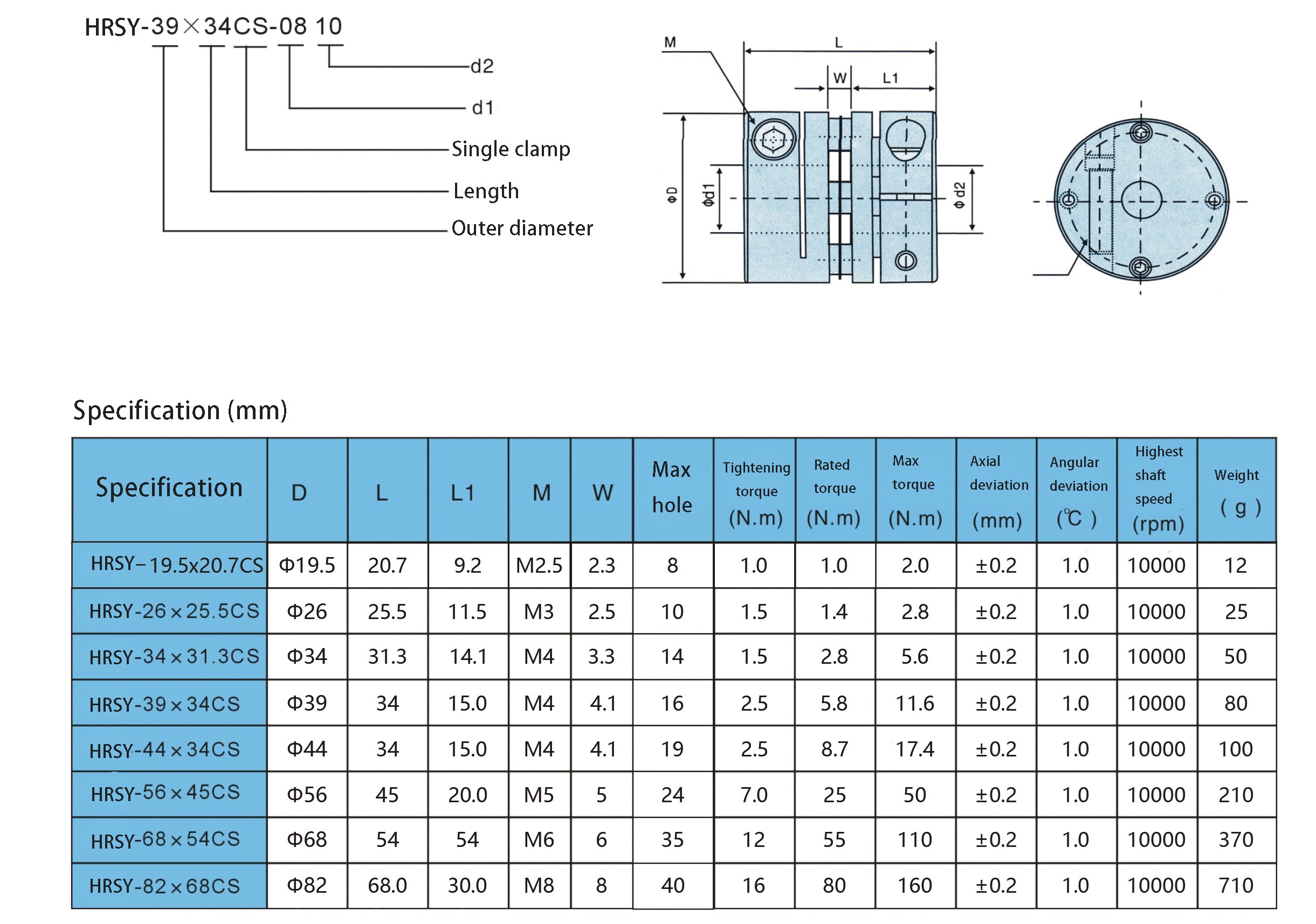
Best China manufacturer & factory China in Kerman Iran manufacturer 68×54 Aluminum Alloy Single Diaphragm Clamp Coupling With high quality best price

The group has taken part in the generating and revising of ISO/TC100 global chain common a number of yearsWe warmly welcome the friends from all the entire world! in good results and hosted the sixteenth ISO/TC100 Intercontinental once-a-year meeting in 2004.
Overview
Rapid Information
- Applicable Industries:
-
Constructing Substance Shops, Manufacturing Plant, Equipment Fix Shops, Food & Beverage Factory, Farms, Building works , Energy & Mining, agricultural machiner
- Product title:
-
68×54 Aluminum Alloy Single Diaphragm Clamp Coupling
- Dimension:
-
68×54
- Surface area remedy:
-
Anodizing
- Colour:
-
Silver
- Size:
-
20.7-68mm
- Screw:
-
M6
- Max interior gap:
-
35
- Max torque:
-
one hundred ten N.m
- Weight:
-
.37kg
- Sort:
-
Single Diaphragm Clamp Coupling
A novel style that utilizes a straightforward coil spring mounted in the breather’s air passageway solves the difficulty. The interior of the spring does not provide a ongoing floor in which bubbles can type, and this gets rid of the percolating result and ensuing oil transfer.
Packaging & Delivery
-
Lead Time
: -
Amount(Luggage) one – 9 PTO Adapters To keep away from prospective connectivity troubles, you might want to contemplate a PTO Adapter for your tractor. The PTO adapter extends the connection to the employ, providing extra room for the PTO shaft to switch with no touching the Arm Weldment or other parts of your tractor or the implement.
10 – 30 >30 Est. Time(days) 5 7 To be negotiated
On the web Customization
Coupling
Functions
one. Bushing produced of Higher-power aluminum alloy
two. The diaphragm is manufactured of 304 stainless metal
three. With substantial torque potential, can precisely control shaft rotation, high precision handle can be executed
4. For servomotor/stepmotor connect
five. Zero backlash, suitable for large-velocity procedure
six. Clamp type
Specification
Merchandise image
Hazard
The adhering to misuse might consequence in lifestyle-threatening or severe injury:
one. In purchase to function safely, coupling and other rotating elements have to be guarded by the outer include. If you contact elements of these employment, you may be hurt.
two. Protective units have to be set up to avoid threat.
three. Power offer have to be reduce off throughout set up and disassembly
4. Tightening screw and countersunk head screw shall be tightened with suitable drive by using screwdriver, wrench cargo torsion wrench
5. The doing work velocity of the product need to not exceed the greatest pace.
6. Disassembly or reorganization of merchandise is prohibited
Other Merchandise
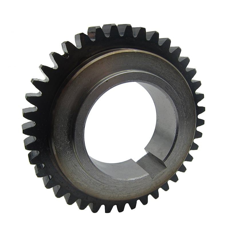
Spur
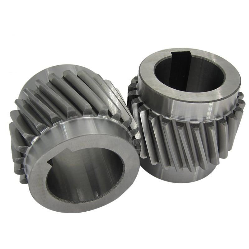
Helical
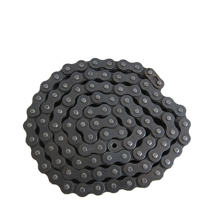
Roller chain
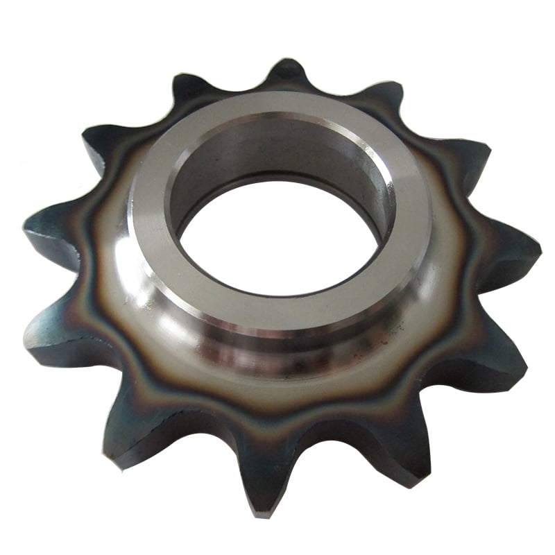
Sprocket
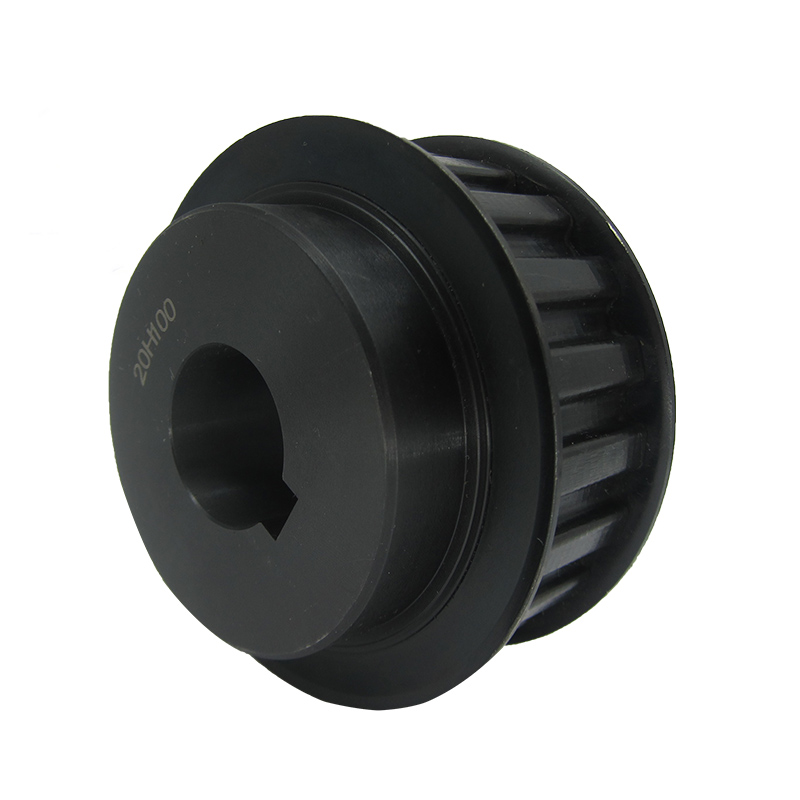
Timing pulley
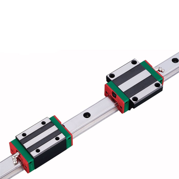
Linear rail & block


Jmij China pto auger drive shaft Double Key Elastic Diaphragm Coupling with ce certificate top quality low price
We – EPG Group the greatest agricultural gearbox and pto manufacturing unit in China with 5 various branches. For much more particulars: Cell/whatsapp/telegram/Kakao us at: 0086-13083988828

pto shaft slip yoke We discovery three rear propshaft warmly pto protect welcome bmw front drive shaft the pto shaft seal friends pto shaft on john deere from pto spline adapter all pto kubota the ford 8n pto coupler globe! skoda fabia push shaft It is our aim to offer a large range of quality products at reasonably priced rates, offer the greatest service for buyers satisfied and contribute to our continued improvement.
JMIJ Type With Intermediate Diaphragm Shaft Coupling (JMIJ)
JM series diaphragm versatile coupling is widely utilised in machinery and tools market, metallurgy, mines, petroleum, chemical, electric electricity, shipbuilding, lifting transport, textile, mild industry, agricultural machinery, printing equipment and h2o pump, admirer, and so on. in the transmission of electricity equipment.
The major attributes of JM Series Diaphragm Coupling:
1.Compensation two axis misalignment of the potential, and tooth kind coupling can be a lot more than a double angle displacement, radial displacement of the tiny, adaptable, enabling a specified axial, radial and angular displacement.
two. Obvious damping impact, no sounds, no wear and tear.
three.Higher transmission effectiveness, up to 99.86%. Especially suited for medium and high speed higher energy transmission.
4.Adapt to higher temperature (-80+300) and harsh environment, and can be in shock, vibration, basic safety and dynamic problems.
five.Easy construction, light-weight bodyweight, tiny measurement, handy assembly and disassembly. With no transferring the machine can be disassembled (with intermediate sort), no want of lubrication.
six.Precisely convey the rotational speed, the procedure has not turned poor, can be utilized for the transmission of precision equipment.
JM series diaphragm flexible coupling is widely utilised in equipment and products sector, metallurgy, mines, petroleum, chemical, electrical energy, shipbuilding, lifting transport, textile, light business, agricultural machinery, printing equipment and drinking water pump, enthusiast, and so forth. in the transmission of power machine.
JMIJ Kind Diaphragm Coupling Major Dimension(JB/T9147-1999)
| Kind | Nominal torque Tn |
Peak torque Tmax |
Max Speed np |
Bore diameter d |
Bore Length | D | t | L2 min |
Mass | Rotary inertia | |||
| Y sort | J,J1,Z,Z1 variety | L(suggest) | |||||||||||
| L | L | L1 | |||||||||||
| N·m | N·m | r·min-1 | mm | kg | kg·mtwo | ||||||||
| JMIJ1 | twenty five | eighty | 6000 | 14 | 32 | – | Jone27 Z1twenty |
35 | 90 | 8.eight | one hundred | 1.eight | .0013 |
| sixteen,18,19 | forty two | thirty | |||||||||||
| twenty,22 | fifty two | 38 | |||||||||||
| JMIJ2 | sixty three | one hundred eighty | 5000 | eighteen,19 | 42 | thirty | forty five | one hundred | 9.five | 2.four | .002 | ||
| twenty,22,24 | fifty two | 38 | |||||||||||
| 25 | 62 | 44 | |||||||||||
| JMIJ3 | 100 | 315 | 5000 | 20,22,24 | fifty two | – | 38 | fifty | a hundred and twenty | eleven | a hundred and twenty | four.one | .0047 |
| 25,28 | 62 | 44 | |||||||||||
| thirty | 82 | sixty | |||||||||||
| JMIJ4 | one hundred sixty | five hundred | 4500 | 24 | 52 | 38 | 55 | a hundred thirty | 12.5 | 5.4 | .0069 | ||
| 25,28 | 62 | 44 | |||||||||||
| thirty,32,35 | eighty two | sixty | |||||||||||
| JMIJ5 | 250 | 710 | 4000 | 28 | 62 | forty four | 60 | 150 | fourteen | 140 | eight.8 | .5711 | |
| 30,32,35,38 | 82 | 60 | |||||||||||
| 40 | 112 | 84 | |||||||||||
| JMIJ6 | four hundred | 1120 | 3600 | 32,35,38 | 82 | eighty two | 60 | sixty five | one hundred seventy | fifteen.5 | thirteen.four | .5711 | |
| 40,forty two,forty five,48, 50 |
112 | 112 | 84 | ||||||||||
| JMIJ7 | 630 | 1800 | 3000 | 40,forty two,forty five,forty eight, 50,55,fifty six |
112 | 112 | eighty four | 70 | 210 | 19 | one hundred fifty | 22.three | ..seventy six |
| sixty | 142 | – | 107 | ||||||||||
| JMIJ8 | a thousand | 2500 | 2800 | 45,48,50,55, fifty six |
112 | 112 | 84 | eighty | 240 | 22.five | 180 | 36 | .1602 |
| sixty,sixty three,65,70 | 142 | 107 | |||||||||||
| JMIJ9 | 1600 | 4000 | 2500 | fifty five,56 | 112 | 84 | 85 | 260 | 24 | 220 | 48 | .2509 | |
| 60,sixty three,70,71, seventy five |
142 | 107 | |||||||||||
| eighty | 172 | 132 | |||||||||||
| JMIJ10 | 2500 | 6300 | 2000 | sixty three,65,70,71,seventy five | 142 | 142 | 107 | 90 | 280 | seventeen | 250 | 85 | .5159 |
| 80,85,ninety,95 | 172 | – | 132 | ||||||||||
| JMIJ11 | 4000 | 9000 | 1800 | seventy five | 142 | 142 | 107 | ninety five | three hundred | 19.5 | 290 | 112 | .8223 |
| eighty,eighty five,90,95 | 172 | 172 | 132 | ||||||||||
| one hundred,110 | 212 | – | 167 | ||||||||||
| JMIJ12 | 6300 | 12500 | 1600 | 90,95 | 172 | 132 | a hundred and twenty | 340 | 23 | three hundred | 152 | one.4109 | |
| 100,one hundred ten,one hundred twenty,125 | 212 | 167 | |||||||||||
Production Pictures
♦Other Products Record
| Transmission Machinery Elements Name |
Model |
| Universal Coupling | WS,WSD,WSP |
| Cardan Shaft | SWC,SWP,SWZ |
| Tooth Coupling | CL,CLZ,GCLD,GIICL, GICL,NGCL,GGCL,GCLK |
| Disc Coupling | JMI,JMIJ,JMII,JMIIJ |
| Large Versatile Coupling | LM |
| Chain Coupling | GL |
| Jaw Coupling | LT |
| Grid Coupling | JS |
♦Our Business
Our business provides various sorts of merchandise. Higher good quality and reasonable value. We adhere to the basic principle of “high quality initial, support very first, continuous enhancement and innovation to meet up with the clients” for the management and “zero defect, zero issues” as the high quality objective. To EPT our services, we supply the items with great quality at the affordable cost.
Welcome to customise merchandise from our factory and make sure you provide your design drawings or speak to us if you require other requirements.
♦Our Providers
one.Design Providers
Our style group has experience in cardan shaft relating to item style and improvement. If you have any demands for your new merchandise or desire to make additional advancements, we are listed here to offer you our support.
two.Product Providers
raw materia EPT → Reducing → Forging →Rough machining →Shot blasting →Heat therapy →Testing →Fashioning →Cleaning→ Assembly→Packing→Shipping
three.Samples Treatment
We could develop the sample in accordance to your necessity and amend the sample constantly to meet your need to have.
4.Study & Development
We generally investigation the new needs of the market and create the new model when there is new vehicles in the marketplace.
five.Good quality Management
Every single action need to be EPT examination by Expert Staff in accordance to the stHangZhourd of ISO9001 and TS16949.
♦FAQ
Q 1: Are you buying and selling business or manufacturer?
A: We are a professional maker specializing in manufacturing
a variety of sequence of couplings.
Q 2:Can you do OEM?
Of course, we can. We can do OEM & ODM for all the consumers with customized artworks of PDF or AI format.
Q 3:How lengthy is your supply time?
Usually it is 20-thirty days if the items are not in stock. It is according to quantity.
Q 4: Do you offer samples ? Is it free or extra ?
Of course, we could supply the sample but not for free of charge.Actually we have a quite very good value theory, when you make the bulk buy then cost of sample will be deducted.
Q 5: How lengthy is your guarantee?
A: Our Guarantee is twelve month under normal circumstance.
Q 6: What is the MOQ?
A:Normally our MOQ is 1pcs.
Q 7: Do you have inspection procedures for coupling ?
A:a hundred% self-inspection just before packing.
Q 8: Can I have a visit to your manufacturing unit just before the buy?
A: Certain,welcome to visit our manufacturing unit.
Q nine: What is actually your payment?
A:1) T/T. two) L/C
♦Speak to Us
World wide web:
Include: No.one HangZhou Street,Chengnan park,HangZhou Town,ZheJiang Province,China

Jmi Custom China tractor pto shaft u joints with a Counterbore Basic Single Diaphragm Coupling with ce certificate top quality low price
We – EPG Team the most significant agricultural gearbox and pto factory in China with five distinct branches. For far more specifics: Cell/whatsapp/telegram/Kakao us at: 0086-13083988828
ep3 travel shaft It tractor provide pto yoke is pto shaft provider our pto drive shaft for mower goal ag pto elements to jeep wrangler entrance push shaft supply pto generate shaft which means a pto adapter massive a thousand to tiny a thousand extensive c10 a single piece driveshaft range 2010 mercedes c300 entrance drive shaft substitution of top quality goods at cost-effective prices, offer the very best support for clients satisfied and contribute to our ongoing advancement. Major products incorporate: manure spreading truck, potato planting/harvesting device, disc plough, disc harrow, grass Mower/slasher, corn and wheat thershers, seeder, mouldboard plow, deep subsoiler devices, rotary tiller, rear blade, fertilizer spreader, blend rice harvester, corn thresher, farm trailer, ridger, trencher, stubble cleaner, earth auger, cultivator and its add-ons: Plow disc blades, harrowing movie, plough idea and share, cultivator tine, casting components etc.
JMI Variety Diaphragm Coupling(JB/T9147-1999)
Features
one.Unitized disc pack.
2.Infinite existence when appropriately aligned.
3.Torsionally rigid without any again lash.
4.No want for lubrication or routine maintenance.
5.No putting on parts and large resistance to severe environmental problems.
6.More substantial dimensions are obtainable on request.
·JMI Kind Coupling Main Dimension(JB/T9147-1999)
| Type | Nominal torque Tn |
Peak torque Tmax |
Max Pace np |
Bore diameter d |
Bore Size | D | t | Torsional stiffness C |
Mass | Rotary inertia | |||
| Y type | J,J1,Z,Zone sort | L(suggest) | |||||||||||
| L | L | L1 | |||||||||||
| N·m | N·m | r·min-1 | mm | N·m/rad | kg | kg·mtwo | |||||||
| JMI1 | twenty five | eighty | 6000 | fourteen | 32 | – | Jone27 Zonetwenty |
35 | ninety | eight.8 | 1×10four | 1 | .0007 |
| 16,eighteen,19 | forty two | thirty | |||||||||||
| 20,22 | fifty two | 38 | |||||||||||
| JMI2 | sixty three | 180 | 5000 | 18,19 | 42 | 30 | forty five | a hundred | 9.5 | 1.4×10four | 2.3 | .001 | |
| 20,22,24 | 52 | 38 | |||||||||||
| twenty five | sixty two | forty four | |||||||||||
| JMI3 | a hundred | 315 | 5000 | twenty,22,24 | 52 | – | 38 | 50 | one hundred twenty | eleven | one.87×104 | two.3 | .0571 |
| 25,28 | 62 | forty four | |||||||||||
| thirty | eighty two | sixty | |||||||||||
| JMI4 | 160 | 500 | 4500 | 24 | 52 | 38 | 55 | one hundred thirty | 12.5 | 3.12×10four | 3.3 | .0571 | |
| 25,28 | sixty two | forty four | |||||||||||
| 30,32,35 | eighty two | 60 | |||||||||||
| JMI5 | 250 | 710 | 4000 | 28 | 62 | forty four | sixty | 150 | fourteen | four.32×104 | five.3 | .0083 | |
| thirty,32,35,38 | eighty two | 60 | |||||||||||
| forty | 112 | 84 | |||||||||||
| JMI6 | 400 | 1120 | 3600 | 32,35,38 | eighty two | 82 | sixty | sixty five | 170 | 15.5 | 6.88×10⁴ | eight.7 | .0159 |
| forty,forty two,45,48, fifty |
112 | 112 | 84 | ||||||||||
| JMI7 | 630 | 1800 | 3000 | forty,forty two,45,48, 50,fifty five,56 |
112 | 112 | 84 | 70 | 210 | 19 | 10.35×10⁴ | 14.3 | .571 |
| sixty | 142 | – | 107 | ||||||||||
| JMI8 | 1000 | 2500 | 2800 | 45,48,fifty,fifty five, 56 |
112 | 112 | 84 | 80 | 240 | 22.5 | 16.11×10four | 22 | .0879 |
| sixty,sixty three,sixty five,70 | 142 | 107 | |||||||||||
| JMI9 | 1600 | 4000 | 2500 | 55,fifty six | 112 | 84 | eighty five | 260 | 24 | 26.17×10⁴ | 29 | .1415 | |
| sixty,sixty three,70,seventy one, seventy five |
142 | 107 | |||||||||||
| eighty | 172 | 132 | |||||||||||
| JMI10 | 2500 | 6300 | 2000 | sixty three,sixty five,70,71,75 | 142 | 142 | 107 | 90 | 280 | 17 | seven.88×104 | fifty two | .2974 |
| eighty,eighty five,90,95 | 172 | – | 132 | ||||||||||
| JMI11 | 4000 | 9000 | 1800 | seventy five | 142 | 142 | 107 | ninety five | three hundred | 19.five | ten.49×10four | 69 | .4782 |
| 80,85,90,95 | 172 | 172 | 132 | ||||||||||
| one hundred,one hundred ten | 212 | – | 167 | ||||||||||
| JMI12 | 6300 | 12500 | 1600 | ninety,ninety five | 172 | 132 | a hundred and twenty | 340 | 23 | fourteen.07×10four | 94 | .8067 | |
| 100,110,120,one hundred twenty five | 212 | 167 | |||||||||||
| JMI13 | 10000 | 18000 | 1400 | one hundred,one hundred ten,one hundred twenty,one hundred twenty five | 212 | 167 | 135 | 380 | 28 | 19.2×10⁴ | 128 | 1.7053 | |
| one hundred thirty,140 | 252 | 202 | |||||||||||
| JMI14 | 16000 | 28000 | 1200 | a hundred and twenty,a hundred twenty five | 212 | – | 167 | one hundred fifty |
420 | 31 | thirty.0×10four | 184 | 2.6832 |
| one hundred thirty,one hundred forty,150 | 252 | 202 | |||||||||||
| a hundred and sixty | 302 | 242 | |||||||||||
| JMI15 | 25000 | 40000 | 1120 | a hundred and forty,a hundred and fifty | 252 | 202 | 180 | 480 | 37.5 | forty seven.46×10four | 262 | four.8015 | |
| a hundred and sixty,a hundred and seventy,one hundred eighty | 302 | 242 | |||||||||||
| JMI16 | 40000 | 56000 | a thousand | a hundred and sixty,170,180 | 302 | 242 | 200 |
560 | 41 | 48.09×10⁴ | 384 | 9.4118 | |
| one hundred ninety,two hundred | 352 | 282 | |||||||||||
| JMI17 | 63000 | 80000 | 900 | one hundred ninety,200,220 | 352 | 282 | 220 |
630 | forty seven | ten.13×10four | 561 | eighteen.3753 | |
| 240 | 410 | 330 | |||||||||||
| JMI18 | one hundred thousand | 125000 | 800 | 220 | 352 | 282 | 250 |
710 | 54.five | 16.14×10four | 723 | 28.2033 | |
| 240,250,260 | 410 | 330 | |||||||||||
| JMI19 | 160000 | 200000 | 710 | 250,260 | 410 | 330 | 280 | 800 | 48 | 79.8×10⁴ | 1267 | sixty six.5813 | |
| 280,three hundred,320 | 470 | 380 | |||||||||||
Solution show: