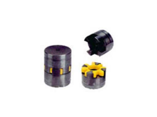
 LXD type single flange star elastic couplingLXD type single flange star elastic coupling is...
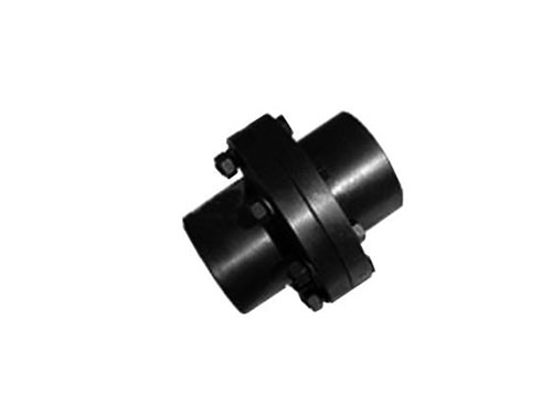 GY, GYS, GYH type rigid couplingThe surface roughness of the coupling means adding...
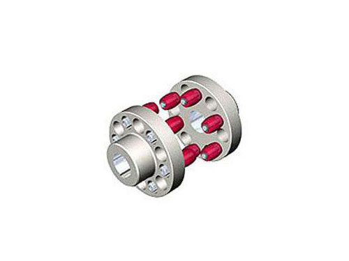 HL type elastic pin couplingThe elastic pin coupling (GB5014-85) is suitable for...
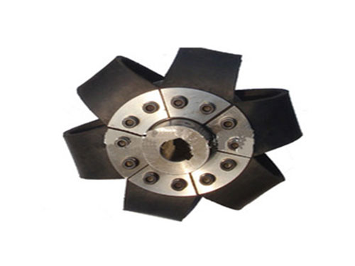 LAK saddle block elastic couplingLAK saddle block elastic coupling is used to connect...
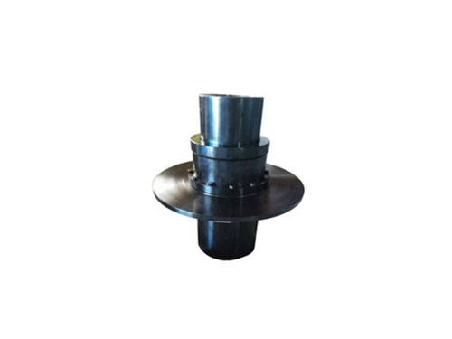 WGP type drum gear coupling with brake discThe gear coupling is made of the same number of teeth...
Briefly analyze the structure design and maintenance of the SL cross slider coupling
When designing the structure of SL Oldham Couplings, based on the size of the transmitted torque, the structure of SL Oldham Couplings and the strength of the hub, determine the range of shaft holes and shafts of the SL Oldham Couplings of various specifications. The allowable speed range of the long SL Oldham coupling of the hole is determined by calculation based on the allowable linear speed and the large outer edge size of the different materials of the SL Oldham coupling. The SL cross slider coupling is also known as the metal SL cross slider coupling. Its slider is ring-shaped and made of steel or alloy. It is suitable for transmissions with low speed and large transmission torque. The SL cross slider coupling is composed of two semi-SL cross slider couplings with grooves on the end faces and an intermediate disk with convex teeth on both sides.Because the convex teeth can slide in the groove, the relative displacement between the two shafts during installation and operation can be compensated.The material of the SL cross slider coupling parts can be 45 steel, and the working surface needs to be heat treated to increase its hardness; Q275 steel can also be used when the requirements are lower, without heat treatment.In order to reduce friction and wear, oil should be injected from the oil hole of the middle plate for lubrication during use.Because the half-SL cross slider coupling and the intermediate disc form a moving pair and cannot rotate relative to each other, the angular velocity of the driving shaft and the driven shaft should be equal.
The SL cross slider coupling needs regular maintenance and replacement:
Power press-in method: This method refers to the use of impact tools or machinery to complete the assembly process. It is generally used in situations where the fit between the SL cross slider coupling and the shaft is transitional or small.The assembly site is usually beaten with a hand hammer. The method is to put wooden blocks or other soft materials on the end surface of the wheel hub as a buffer, and rely on the impact force of the hand hammer to knock the SL cross slider coupling in.
Static press-in method: This method uses clamps, jacks, manual or motorized presses according to the required press-in force during assembly. The static press-in method is generally used for tapered shaft holes.Because the static press-in method is restricted by the pressure machine, it is difficult to apply a large force when the interference is large.At the same time, the uneven small peaks on the mating surface between the SL cross slider coupling and the shaft will be cut off during the press-in process, causing the mating surface to be damaged.Therefore, this method is generally not widely used.