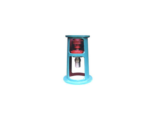
 TB type HG5-251-69 standard rackThe standard frame of TB type HG5-251-69 is "glass-lined...
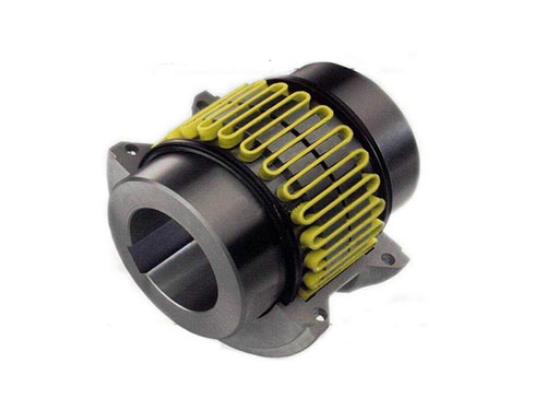 JSZ type brake wheel couplingThe structure of JSZ type brake wheel coupling...
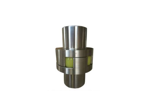 ML plum-shaped elastic couplingML plum-shaped elastic coupling and other coupling...
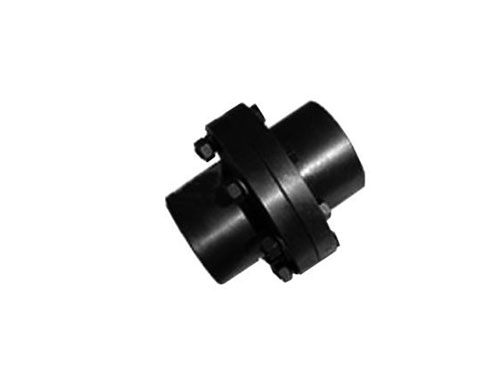 GY, GYS, GYH type rigid couplingThe surface roughness of the coupling means adding...
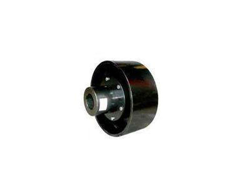 LTZ elastic sleeve pin coupling with brake wheelLTZ (formerly TLL type) with brake wheel elastic sleeve pin...
The installation details of the plum blossom coupling and the conclusion of the coupling of the diaphragm coupling
Some details of the installation of the plum blossom coupling are not very clear. Here is a brief introduction for you:
10. Before installation, check whether the two shafts of the prime mover and the working machine are concentric, whether there are wrapping paper and scratches on the surfaces of the two shafts, whether there are debris in the inner holes of the two half couplings of the plum coupling, and whether the edges of the inner holes are If there are bruises, the shaft and half coupling should be cleaned up, and the bruises should be treated with a fine file.Then check whether the inner hole diameter and length of the two half couplings are consistent with the diameter and shaft elongation of the prime mover and working machine.In general selection, it is better to make the length of the prime mover and the working machine end half-coupling less than the shaft extension of 30-XNUMXmm.
XNUMX. Instructions for operators: Before starting the equipment, check whether the nut of the plum coupling is loose or falling off. If so, tighten the nut with a wrench in time.
250. Alignment: use a dial indicator to detect the run-out of the flange end and outer circle of the two halves of the coupling. When the outer circle of the flange is less than 0.05mm, the run-out value should not be greater than 250mm; when the outer circle of the flange is greater than 0.08mm , The jitter value should not be greater than XNUMX.
XNUMX. Install the bolts: insert the bolts from the outside of the small hole of the flange, pass through the outside of the large hole of the other flange, put on the buffer sleeve, elastic washer, twist the nut, and tighten the nut with a wrench.If the installation is unsuitable or dismantle and replace without damaging the shaft and the half coupling, it is better to rotate freely after installation.
120150. In order to facilitate the installation, it is good to put the two half couplings in the 34 insulation box or oil tank for preheating, so that the inner hole size increases and it is easy to install.After installation, make sure that the shaft head cannot protrude from the end face of the half coupling, and it is better to be flush.Detect the distance between the two halves of the coupling: 0 points of readings measured along the two inner sides of the flange of the half coupling are averaged, and the sum of the measured dimensions of the extension and the two diaphragm sets is controlled by the error. Within the range of 0.4-XNUMXmm.
The mold forming of the plum blossom coupling shell simplifies the processing technology, and the cost is low. The larger the tooth width, the larger the drum radius, the larger the backlash required, and it is commonly used in various hydraulic pumps, lubrication pumps, pneumatic pumps, etc. Compressors, textile machines and other machinery.
The misaligned rotor-bearing system of the diaphragm coupling coupling is used as the object, and the generalized inverse iteration method is used to analyze the influence of misalignment on the dynamic and static characteristics of the symmetrical rotor system bearing and the inherent characteristics of the system. The main conclusions are as follows:
XNUMX. The stability of the system tends to deteriorate due to the misalignment of the bearings on both sides of the diaphragm coupling.Under the influence of misalignment, the smaller logarithmic decay rate of the system is reduced, and the instability speed drops.
XNUMX. The impact of the misalignment of the bearings on both sides of the coupling and the two ends of the system on the load distribution of the system is different.The load distribution supported on both sides of the coupling increases with the increase of the misalignment, and decreases under the influence of the misalignment of the bearings at both ends of the system.The load distribution at the bearings at both ends of the system decreases with the increase of the misalignment at the supports on both sides of the coupling, and increases under the influence of the misalignment at its own.Due to the vibration isolation function of the diaphragm coupling, the misalignment at the support of the rotor system of one span has less effect on the dynamic and static characteristics of the rotor bearing of the other span.
XNUMX. The inherent characteristics of the system change under the action of the misalignment, in which the corresponding value of the real part of the eigenvalue decreases, while the imaginary part increases, and the first few modes of the system no longer exhibit symmetrical or antisymmetric characteristics , The deformation of one of the rotors is the main one, and the other one hardly deforms.