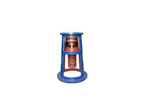
 TJQ frameThe choice of TJQ type frame is basically...
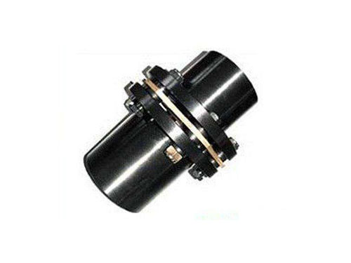 JMⅡ type non-counterbore basic diaphragm couplingJMⅡ type non-counterbore basic diaphragm coupling...
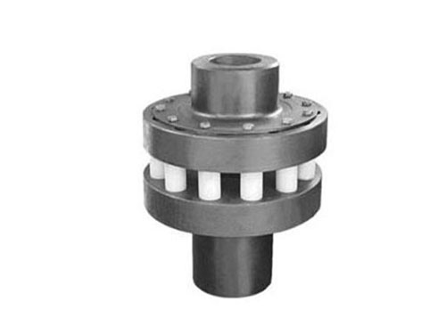 HL type elastic pin couplingThe elastic pin coupling uses a number of non...
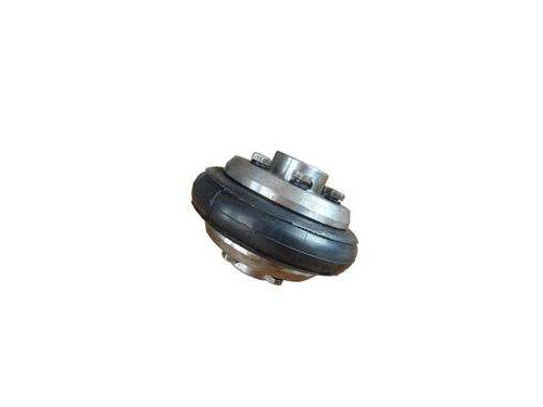 Tire coupling for LLA metallurgical equipmentThe tire coupling for LLA metallurgical equipment is...
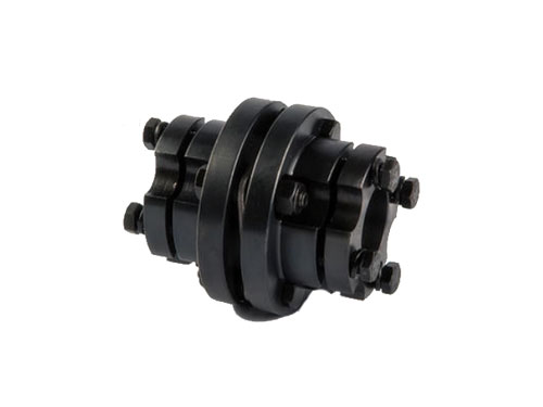 DJM expansion sleeve diaphragm couplingDJM expansion sleeve diaphragm coupling strength JZMJ type...
The assembly method and use environment of the diaphragm coupling
The assembly method of the diaphragm coupling is to check the original effect and whether the two shafts of the operating machine are aligned before assembly, whether there are wrapping paper and bruises on the surface of the two shafts, and the inner holes of the two half couplings of the coupling Whether there are miscellaneous goods, whether there are bruises on the edge of the inner hole, if any, the shaft and half coupling should be cleared and pickled, and the bruises should be solved with a fine file.Then check whether the inner hole diameter and length of the two half-couplings are consistent with the original effect, the diameter of the manipulator, and the length of the shaft.
During the normal selection, it is better to make the original effect and the length of the half-coupling at the end of the operating machine smaller than the length of the shaft extension by 10-30mm.In order to facilitate the assembly, the two half couplings are placed in the fresh-keeping tank or the oil tank to complete the heat transfer, which makes it difficult to install the inner hole.After assembly, make sure that the shaft head cannot protrude from the end face of the half coupling, and it is better to be flush.Detect the interval between the two halves of the coupling: 34 points are measured along the two inner sides of the flange of the half coupling to take the uniform value, and the sum of the measured dimensions of the enlarged section and the two diaphragm sets is the error between the two It is within the range of 0-0.4mm.It is to use a dial indicator to detect the end face and outer circle of the flange of the two halves of the coupling. When the outer circle of the flange is less than 250mm, the value of the flop should not be greater than 0.05mm; when the outer circle of the flange is greater than 250mm, the flop The value should not be greater than 0.084. Assemble the nut, insert the nut from the outside of the small hole in the flange, and pass through the outside of the large hole of the other flange. Put on the buffer sleeve, elastic sealing ring, twist on the screw nut, and use the handle. Tighten the screw nut.
Diaphragm coupling is a kind of high-performance metal elastic element coupling. It consists of a sleeve in the middle, diaphragm sets on both sides, and half couplings alternately connected by reaming bolts. The diaphragm set is composed of multiple The sheet is so thin that it is made of stainless steel, and the diaphragm assembly can be divided into two types: connecting rod type and integral type according to different structures.The diaphragm coupling relies on the elastic deformation of the diaphragms on both sides to compensate for the relative displacement of the two connected shafts. The main features are no lubrication, a compact structure, a good degree of goodness, a good service life, no rotation gap, and no temperature and oil pollution. influences.
Diaphragm couplings are suitable for shafting transmission in high temperature and corrosive medium conditions, and are commonly used for shafting transmissions of various mechanical devices, such as water pumps (high-power, chemical pumps), fans, compressors, hydraulic machinery , Petroleum machinery, printing machinery, textile machinery, chemical machinery, mining machinery, metallurgical machinery, naval power transmission systems, after being dynamically balanced, they have been widely used in transmission shaft systems.
Coupling refers to a device that connects two shafts or shafts and rotating parts, and rotates together in the process of transmitting motion and power, and does not disconnect under normal circumstances.The axis of the coupling is skewed so that the coupling cannot enter. Only the axis, the position of the coupling hole and the shaft, and the position of the collision block can be accurately calibrated.The impact point should be selected, and the first two hits should be light. When the person leaves about one-third of the distance, you can slam hard to prevent the connection part from bearing excessive load and play the role of overload protection.There are two types of couplings: cold installation and hot installation.
When precision parts such as bearings and mechanical seals have been pre-installed on the main shaft, it is forbidden to hit and impact the coupling to avoid damage to the machine parts.Such as pulleys falling off due to loose position, hoist chain slipping, insufficient fuel, fire alarm, etc.Pay more attention in advance and check carefully during the preparation and operation phases of the tool.The coupling does not have the ability to buffer and compensate for the relative displacement of the dual axis. It requires strict alignment of the dual axis. However, this type of coupling has simple structure, reasonable manufacturing cost, convenient disassembly and assembly, and convenient maintenance. The dual axis has a relatively good centering. It has a large transfer moment and is widely used.
Couplings are divided into flexible couplings without elastic elements and flexible couplings with elastic elements. They only have the ability to compensate for the relative displacement of the two axes, but they cannot cushion and dampen vibration. Commonly used are slider couplings and gear couplings. The latter type, such as universal couplings and chain couplings, contain elastic elements. In addition to the ability to compensate for the relative displacement of the two axes, they also have buffering and damping effects, but the transmitted torque is limited by the goodness of the elastic elements. Generally inferior to flexible couplings with elastic elements.The size of the transmitted load and the shaft speed are not high. Due to reasons such as manufacturing, installation, load deformation and temperature changes, it is difficult to maintain strict alignment of the two shafts after installation and adjustment.
When the radial displacement is large, the slider coupling can be selected, and when the angular displacement of the intersecting two shafts is large, the universal coupling, etc. can be selected.In the working process, when there is a large relative displacement between the two shafts, a flexible coupling should be selected.Whether the working speed of the coupling is high or not and the size of the centrifugal force caused to choose the type of coupling, for the transmission shaft should choose a coupling with good balance accuracy.When it is required to reduce the severe impact load of the torsional vibration of the shaft system or the coupling is selected for the transmission system, the tire coupling with good shock absorption and buffering performance and good performance of offset compensation between shafts can be selected to adapt to the impact occasion.