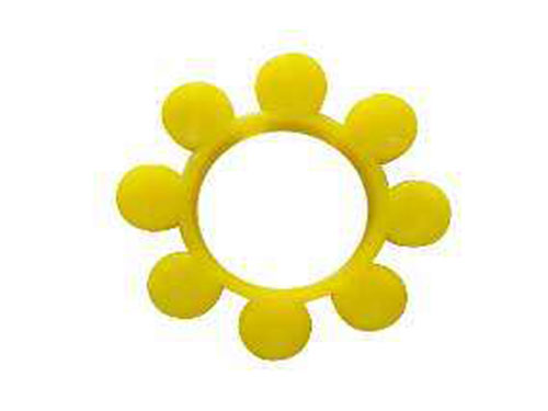
 GR-shaped coupling elastic bodyGR-shaped coupling elastic body and star-shaped elastic...
 FZ type double fulcrum square bottom plate rackFZ type double fulcrum square bottom plate rack series is suitable for...
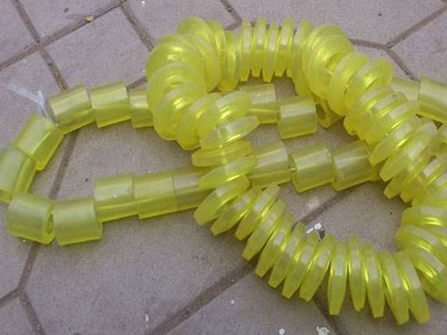 Elastic sleeveThe elastic sleeve uses a number of non-metal elastic...
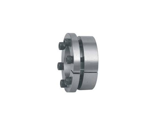 Expansion coupling sleeveCompared with the key connection, the expansion sleeve connection has...
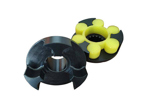 LMZ-ⅡPlum-shaped elastic coupling with brake wheelLMZ-Ⅱ (formerly MLL-Ⅱ) type with brake wheel plum...
The structure of universal coupling and the normal selection of diaphragm coupling
The universal joint is composed of two single universal joints and an intermediate shaft. It can be used to realize the connection between the two shafts that are intersecting, parallel or spatially staggered to realize the movement and power between the driving shaft and the driven shaft. Of delivery.It plays an important role in the development of mechanical engineering and vehicle industry.Since the angular velocity of the driven shaft of the single universal joint is changed periodically, additional dynamic load will be caused in the transmission and the shaft will vibrate. However, the use of double universal joint can eliminate this shortcoming.The pneumatic clutch of the universal coupling, the main motor, and the slow device must be carefully checked to remove bumps and burrs during transportation; they can be installed after cleaning.
The coaxiality and inclination of the drive shaft of the pinion gear device and the main motor shaft are 1/1000, and should be consistent with the inclination direction of the ball milling book L. The inclination and height can be adjusted by adding a gasket under the motor base; If there is an error in the parallelism, the bearing position of the movable motor rotor can be adjusted. The adjustment should be careful and strive for good accuracy; the axial position should be adjusted in place according to the requirements of the drawing.When installing the slow speed device, make sure that after the planetary cycloid reducer with motor is installed, the pull rod device can easily move the claw clutch, and there should be no jamming, indisengagement, and poor reliability. Achieve flexible clutch.
The contact and disconnection of the travel switch and the stop block, the surface of the axially moving semi-universal coupling and the bushing relative to the sliding surface, the sliding block of the pull rod device and the contact surface of the matching groove should be coated with grease .The parallelism between the pinion axis of the ball mill and the axis of the barrel of the ball mill does not exceed 0.15/1000.When installing the universal coupling gear cover, check whether the gear cover is collided or deformed during long-distance transportation, and whether the oil paint is not afraid of falling off or deformed, and repairing is not afraid of oil paint.When installing the gear cover, pay attention to inspection and correction, make sure that no collision occurs during the gear operation, and make sure that the felt ring is close to the big gear when looping, and no gap is allowed.
Diaphragm couplings are widely used in heavy industry and light industry because of their excellent formability, compatibility, and good toughness in a wide temperature range.Compared with the gear coupling, the diaphragm coupling does not need to be smooth, sealed, noiseless, maintenance is not required at all, and the production is more convenient.The diaphragm coupling has the function of compensating for the offset of the two axes in the normal operation.The diaphragm coupling relies on the elasticity of the diaphragm to compensate for the displacement of the two shafts. The diaphragm coupling is commonly used for shaft transmission of different types of machinery and equipment.
Diaphragm couplings transmit torque in the same way. The diaphragm itself is very thin, and it is difficult to bend when displacement occurs, so it can accept up to 15 degrees of deflection, and at the same time, a relatively high bearing load occurs in the servo system. .The elastic part of the diaphragm is a diaphragm assembly that is decomposed by a thin stainless steel diaphragm stack. The diaphragm generally has a waist type, a multi-faceted ring and other internal shapes, and a fine nut discrimination and master-slave method on a uniformly scattered circle. Lan connection.
The diaphragm coupling has the characteristics of no sliding, no lubrication, long service time, no noise, no fear of acid, alkali, and corrosion resistance. It can be used in high temperature, cold, oil, water and corrosive media.Diaphragm couplings are suitable for medium and large torque shaft transmissions. Different types of machinery and devices have little load and good versatility.
Before assembly, check whether the original effect and the two shafts of the operating machine are aligned, whether there are wrapping paper and scratches on the surface of the two shafts, whether there are sundries in the inner holes of the two half couplings of the coupling, and the edges of the inner holes can be Whether there is bruise, if so, the shaft and half coupling should be resolved. Can the diameter and length of the inner hole of the two half coupling be consistent with the original effect, the diameter of the manipulator and the shaft enlargement.Diaphragm coupling is used to detect the end face and outer circle of the flange of the two halves of the coupling with a dial indicator. When the outer circle of the flange is less than 250mm, the value should not be greater than 0.05mm; when the outer circle of the flange is greater than 250mm When, the value should not be greater than 0.08mm.After the diaphragm coupling is assembled, make sure that the shaft head cannot protrude from the end face of the half coupling, and it is better to be flush.
When the diaphragm coupling is selected normally, make the original effect and the length of the half-coupling at the end of the manipulator less than 10-30mm of its shaft expansion.In order to facilitate the assembly, put the two half couplings in the fresh-keeping box or the oil tank to complete the heat transfer, so that the inner hole is enlarged and installed.In the detection of the interval between the two halves of the coupling, the readings of 3 and 4 points are measured along the two inner sides of the flange of the half coupling to take the uniform value, and the error between the two is controlled within the range of 0-04mm.Diaphragm couplings are often heated and disassembled with hydraulic jacks.