 FZ type double fulcrum square bottom plate rackFZ type double fulcrum square bottom plate rack series is suitable for...
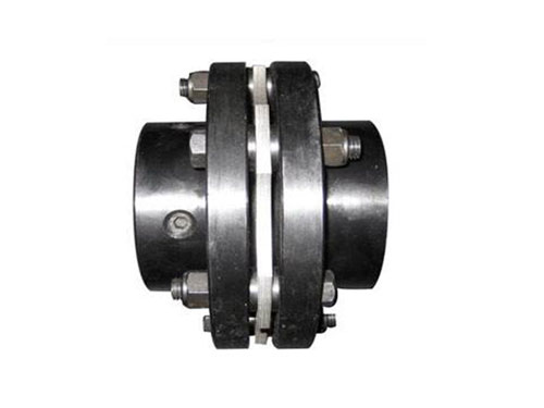 DJM type diaphragm couplingDiaphragm coupling forging materials need to be inspected...
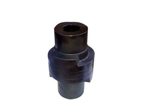 Slider couplingSlider couplings are often used in general...
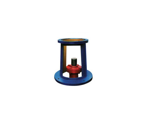 JAI large flange frame <69 standard>, JAII <69 standard> frameThe JAI large flange frame itself has no shaft support...
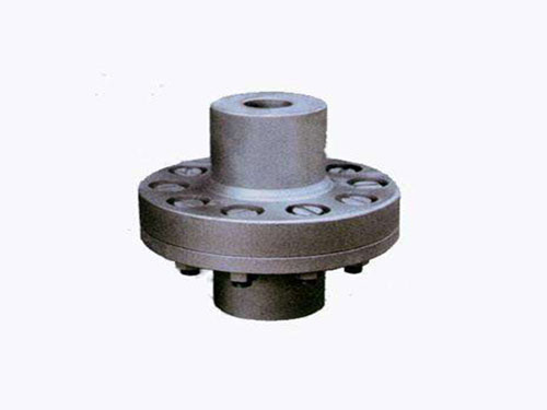 Elastic sleeve pin coupling for pumpElastic sleeve pin coupling for pump: 1. Elastic...
Performance characteristics of serpentine spring coupling and stress analysis of diaphragm coupling
The serpentine spring coupling is a structural metal.It relies on serpentine springs to transmit torque.The serpentine spring coupling is a relatively common shaft coupling transmission component in the field of global machinery today, and it is also a particularly versatile shaft coupling transmission component.The serpentine spring coupling transmits torque by inserting the serpentine spring into the tooth slots of the two halves of the coupling.During operation, the axial force of the active end tooth facing the snake spring drives the driven end to transmit torque, which largely avoids the occurrence of resonance. Moreover, the elastic variable produced by the reed when transmitting torque enables the mechanical system to be able to transmit torque. Get a good damping effect.
Performance characteristics of serpentine spring coupling:
47. The transmission speed of the coupling is determined to reach XNUMX%, and its short-term overload capacity is twice the rated torque, and the operation is stable.
70. Disassembly and assembly are easy to disassemble, the whole machine has fewer parts, small size and light weight. The spring sheet designed as a trapezoidal section and the trapezoidal tooth groove are particularly convenient and close, so that the assembly and disassembly and maintenance are better than ordinary couplings. Simple.There is also a brand-new disassembly and assembly coupling, which adopts a conical surface connection and uses several bolts on the end surface to apply force to achieve the connection effect when the expansion function is realized.It can be used for interference when installed in gaps, and it can save more than XNUMX% of time by cooperating with old-fashioned interference products.
36. Protection equipment with good anti-shock and vibration reduction. Since the spring leaf and the tooth arc surface are in point contact, the coupling can obtain greater flexibility.It can be installed to work normally under conditions of radial, angular and axial deviations at the same time.And it can absorb a large amount of vibration force through the flexible transmission of the spring, and the cushioning effect reduces the impact vibration by more than XNUMX%. It is a transmission impact filter.
XNUMX. The serpentine spring sheet of the trapezoidal section of the serpentine spring coupling is made of high-quality spring steel. After strict heat treatment, the surface of the spring is sandblasted to compress the surface structure molecules to achieve the effect of anti-wear and long life.This has good mechanical properties so that the service life of the coupling is much longer than that of the non-metal elastic element coupling.
XNUMX. The tooth surfaces of the two half couplings in contact with the reeds are arc-shaped. When the transmission torque increases, the springs will deform along the tooth arcs, so that the force points of the two half couplings on the reeds are close .Therefore, it has a larger load variation than general elastic couplings.The buffering effect produced by the transmission force when the reed deforms along the tooth arc, especially when the machine is started or when the impact load, protects the stability of the supporting parts to a corresponding degree.
XNUMX. Simple structure and easy maintenance. The aluminum alloy casing protects the spring from being thrown out during operation, and the casing is filled with butter, which not only makes the lubrication good, but also makes the noise of the reed meshing absorbed by the butter damping.There is no special periodic maintenance during normal use. As long as the amount of grease is sufficient during installation, the whole grease can absorb the corresponding noise caused by the transmission, and the grease can be properly supplemented after long-term work.
For the stress analysis of the diaphragm coupling:
XNUMX. Centrifugal stress Assuming that the bolt and the diaphragm are of the same material, the respective masses can be calculated. According to the position and the spiral angle, the centrifugal force can be calculated, and it acts on the total center of mass.
XNUMX. The bending stress caused by radial and angular displacements causes the diaphragm to undergo periodic bending deformation along the axial direction due to the actual installation error in the axial angle direction, and it is the main factor determining the fatigue life of the diaphragm, and the angle can be tilted. Find the size of the restoring torque.
XNUMX. When the diaphragm transmits torque, the torque is transmitted along the tangent direction of the bolt distribution circle through the active bolt and the diaphragm element to drive the driven bolt.Ignoring the slight relative movement between the diaphragms, it is considered that each diaphragm bears the torque evenly.When the elastic diaphragm coupling transmits torque, the diaphragm plane is stressed. The shaded circle represents the input of the active end, and the blank circle represents the output of the driven end.
0. Membrane surface stress (torque stress, suppose the transmission torque is T(N8m), the total number of pieces is m, for 4-hole bolts, from the simplified conditions, T single piece = Tlm, each main bolt received The force is F=TlXNUMXmR.
XNUMX. The bending stress caused by the axial displacement causes the diaphragm to be bent and deformed along the axial direction due to the installation error in the axial direction. The axial force can be calculated by the magnitude of the axial displacement.
Briefly describe the selection principle of diaphragm coupling:
XNUMX. Diaphragm couplings are often used in servo systems. Diaphragms have good torque rigidity, but are slightly inferior to bellows couplings.
XNUMX. Adjust the model according to the shaft diameter: The initially selected coupling size of the bearing coupling, that is, the shaft hole diameter d and the shaft hole length L, should meet the requirements of the shaft diameter of the driving and driven ends, otherwise it must be adjusted according to the shaft diameter d The specifications of the coupling.
1.5. Diaphragm couplings are a bit like bellows couplings. In fact, couplings transmit torque in the same way.The diaphragm itself is very thin, so it is easy to bend when the relative displacement load is generated, so it can withstand up to XNUMX degrees of deviation, while generating a lower bearing load in the servo system.
XNUMX. Diaphragm coupling consists of at least one diaphragm and two shaft sleeves.The diaphragm is fastened to the shaft sleeve with a pin and generally does not loosen or cause backlash between the diaphragm and the shaft sleeve.Some manufacturers provide two diaphragms, and some provide three diaphragms, with one or two rigid elements in the middle, and the two sides are connected to the shaft sleeve.
XNUMX. Diaphragm couplings are especially delicate, and they are easily damaged if they are misused or not installed correctly during use.