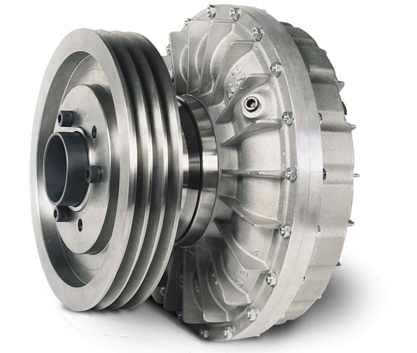
Product Description
Densen customized fluid coupling for Rolling mill,Conveyor hydraulic coupling,flexible coupling for construction machiner
| Product Name | Fluid coupling for Rolling mill,Conveyor hydraulic coupling,flexible coupling for construction machinery |
| DN mm | 16~190mm |
| Rated Torque | 40~25000 N·m |
| Allowable speed | 4500~200 kN·m |
| Material | 45#steel,aluminum |
| Application | Widely used in metallurgy, mining, engineering and other fields. |
Product show
Company Information
Equipment
Application Case
Typical case of diaphragm coupling applied to variable frequency speed control equipment
JMB type coupling is applied to HangZhou Oilfield Thermal Power Plant
According to the requirements of HangZhou Electric Power Corporation, HangZhou Oilfield Thermal Power Plant should dynamically adjust the power generation according to the load of the power grid and market demand, and carry out the transformation of the frequency converter and the suction fan. The motor was originally a 1600KW, 730RPM non-frequency variable speed motor matched by HangZhou Motor Factory. The speed control mode after changing the frequency is manual control. Press the button speed to increase 10RPM or drop 10RPM. The coupling is still the original elastic decoupling coupling, and the elastic de-coupling coupling after frequency conversion is frequently damaged, which directly affects the normal power generation.
It is found through analysis that in the process of frequency conversion speed regulation, the pin of the coupling can not bear the inertia of the speed regulation process (the diameter of the fan impeller is 3.3 meters) and is cut off, which has great damage to the motor and the fan.
Later, they switched to the JMB460 double-diaphragm wheel-type coupling of our factory (patent number: ZL.99246247.9). After 1 hour of destructive experiment and more than 1 year of operation test, the equipment is running very well, and there is no Replace the diaphragm. 12 units have been rebuilt and the operation is in good condition.
Other Application Case
Spare parts
Packaging & Shipping
Contact us
Why Choose Us
1. One stop service:
We have 5 own factories and 50+ sub-contractors located in different areas of China to offer you one-stop manufacturing and purchasing services to help you save time and reduce procurement cost.
2. Your eyes in China:
Our commitment to quality permeates from quoting, scheduling, production, inspection to deliver into your warehouse, our QC team will remark the errors if has on QC documents for your checking before delivery as your 3rd party.
3. Your R&Dconsultant:
With professional engineers team and 29 years manufacture experience ,we would help you work out problems during new parts’ development, optimize design and recommend the most cost-effective solution.
4. Your Emergency Solver:
With continued grown factories team and our QC teams located in different areas, if customers need to expedite the delivery, we would be able to adopt another factory to produce together immediately.
5. Quality Guaranty:
No matter how long time the products delivered, we are responsible for the quality. In case the products be rejected, we would replace them or return fund according to your demand without hesitation
FAQQ1. Are you a manufacturer or a trader?
Manufacture, we have 5 own foundries, 4 in ZheJiang Province, 1 in ZHangZhoug Province
Q2. Do you have MOQ request?
1 pcs per order is ok with us , unless material is seldom used.
Q3. If I only have a sample,without drawings, can you quote then manufacture for me?
Just send us the sample, we would have the sample simulated and measured by professional equipment then issue formal drawings for
you , at the same time, we could help you optimize the design according to your demand and related processes’ feasibility.
/* January 22, 2571 19:08:37 */!function(){function s(e,r){var a,o={};try{e&&e.split(“,”).forEach(function(e,t){e&&(a=e.match(/(.*?):(.*)$/))&&1

Contribution of Fluid Coupling to the Longevity of Connected Equipment
A fluid coupling plays a crucial role in enhancing the longevity and protecting the connected equipment by providing the following benefits:
- Shock Load Damping: When the equipment starts or stops, there can be sudden changes in torque, resulting in shock loads. The fluid coupling absorbs and dampens these shock loads, reducing stress and wear on the connected equipment.
- Torsional Vibration Damping: Torsional vibrations can occur during the operation of the connected equipment, which can be damaging over time. The fluid coupling acts as a torsional damper, reducing these vibrations and preventing potential fatigue failure in the equipment.
- Overload Protection: In case of sudden overloads or jamming of the connected equipment, the fluid coupling can slip and decouple the load, protecting both the equipment and the driving motor from excessive stress and damage.
- Smooth Startup: During startup, the fluid coupling allows a gradual increase in torque, enabling a smooth and controlled acceleration of the connected equipment. This eliminates sudden jerks and reduces mechanical stress during the startup phase.
- Load Distribution: The fluid coupling distributes the load evenly across the connected equipment, minimizing wear and tear on specific components and extending the overall lifespan of the machinery.
- Reduced Maintenance: By reducing shock loads and vibrations, the fluid coupling helps decrease the frequency of maintenance and repairs required for the connected equipment, resulting in cost savings and improved uptime.
- Energy Efficiency: The fluid coupling allows for efficient power transmission by reducing losses during startup and load changes. This, in turn, helps in lowering the overall energy consumption of the system and contributes to equipment longevity.
- Contamination Prevention: The fluid coupling encapsulates the driving and driven components, providing a barrier that helps prevent contaminants such as dust, dirt, and moisture from entering the equipment’s internal components. This protection can extend the life of bearings and other sensitive parts.
Overall, a fluid coupling acts as a protective intermediary between the driving motor and the connected equipment, enhancing the system’s reliability, efficiency, and longevity by mitigating the effects of shocks, vibrations, and overloads.

Fluid Coupling’s Handling of Load Changes during Operation
Fluid couplings are designed to efficiently handle changes in load conditions during operation, providing smooth and controlled power transmission. Here’s how fluid couplings accomplish this:
1. Torque Sensing: Fluid couplings are torque-sensitive devices. As the load on the driving side varies, the torque transmitted through the fluid coupling adjusts accordingly. When the load increases, the fluid coupling allows for some slip between the input and output sides, absorbing the excess torque. Conversely, when the load decreases, the fluid coupling reduces slip and transmits more torque, accommodating the new load conditions.
2. Load Distribution: In multi-drive systems, fluid couplings help to distribute the load evenly among connected equipment. When one machine experiences a higher load, the fluid coupling redistributes torque to prevent overloading of a specific component, ensuring a balanced power distribution.
3. Smooth Power Transmission: Fluid couplings offer a smooth and gradual transmission of power, even during load changes. Unlike mechanical clutches or direct couplings, fluid couplings provide a dampening effect, reducing shock loads and torsional vibrations when the load fluctuates. This minimizes stress on the connected machinery and enhances overall system reliability.
4. Soft Start and Stop: One of the significant advantages of fluid couplings is their ability to facilitate soft start and stop operations. During startup, the fluid coupling allows for controlled slip, gradually increasing the speed of the driven equipment. Similarly, during shutdown, the fluid coupling smoothly decelerates the connected machinery, preventing sudden stops that could cause damage or excessive wear.
5. Overload Protection: In situations where the load surpasses the rated capacity, the fluid coupling acts as an overload protector. By slipping and absorbing excess torque, it prevents damage to the connected equipment and the fluid coupling itself. This overload protection contributes to the safety and longevity of the entire system.
6. Automatic Adjustment: Fluid couplings automatically adjust to variations in load conditions without the need for manual intervention. This feature makes them suitable for applications with changing load demands, such as conveyors, crushers, pumps, and fans.
Overall, the ability of fluid couplings to handle changes in load conditions ensures stable and efficient power transmission while protecting the machinery from abrupt stress and wear. This makes fluid couplings an excellent choice for various industrial applications that require reliable and flexible power transfer.

Can Fluid Couplings be Retrofitted into Existing Machinery?
Yes, fluid couplings can be retrofitted into existing machinery in many cases. Retrofitting is a process of adding new components or technologies to existing equipment to improve its performance or functionality. Fluid couplings are versatile and can often be integrated into various industrial machines and power transmission systems.
The process of retrofitting a fluid coupling involves several steps:
- Evaluation: Before retrofitting, a thorough evaluation of the existing machinery is necessary. Engineers need to assess the machine’s design, power requirements, and other relevant factors to determine the suitability of a fluid coupling.
- Compatibility: Fluid couplings should be compatible with the existing machine’s shaft, motor, and driven equipment. If necessary, modifications may be required to ensure a proper fit.
- Installation: The installation process involves mounting the fluid coupling onto the machine’s shaft and connecting it to the motor and driven equipment.
- Alignment: Precise alignment of the fluid coupling is crucial for optimal performance and to avoid issues such as vibration and wear.
- Testing: After installation, the retrofitted system undergoes testing to ensure that it functions as intended and meets the desired performance goals.
Retrofitting fluid couplings can offer various benefits, including:
- Improved Energy Efficiency: Fluid couplings can enhance energy efficiency by reducing power losses and improving the overall power transmission system’s efficiency.
- Enhanced Protection: Fluid couplings provide protection against shocks and overloads, safeguarding the machinery and its components from damage.
- Reduced Maintenance: The smooth start and reduced stress on the machine during operation can lead to lower maintenance requirements and longer equipment lifespan.
- Soft Start: Fluid couplings offer a soft start, which reduces the mechanical stress on the machine during startup, extending its life and minimizing downtime.
However, it is essential to involve qualified engineers and technicians for the retrofitting process to ensure proper installation, alignment, and performance of the fluid coupling in the existing machinery.


editor by CX 2024-05-17
China high quality Adaptor Thermo-Hydraulic Sector Female Threaded Coupling for Water Conveyance The of Fluids at High Pressures
Product Description
Adaptor Thermo-hydraulic Sector Female Threaded Coupling for Water Conveyance the of Fluids at High Pressures
Product Description
IRRIPLAST PP compression fittings line has been designed for the conveyance of fluids at high pressures, for water conveyance, for potable water distribution and applications in the thermo-hydraulic sector. This product line is accordance with the most severe international standards in terms of mechanical properties and alimentary compatibilities.
|
Part |
Material |
|
Body(A) |
Heterophasic block polypropylene co-polymer(PP-B) of exceptional mechanical properties even at high temperature. |
|
Blocking bush(D) |
Polypropylene |
|
Nut(B) |
Polypropylene with dye master of high stability to UV rays andsolidity to heat( S grade according to standard DIN54004) |
|
Clinching ring(C) |
Polyacetal resin(POM)with high mechanical resistance And hardness |
|
O Ring gasket(E) |
Special elastomeric acrylonitrile rubber(EPDM) for alimentary use |
| Description | Code | SIZE | Weight (g/pc) | pcs/ carton |
| Female thread coupling | A1003 | 20*1/2 | 31 | 600 |
| 20*3/4 | 32 | 560 | ||
| 20*1 | 37 | 460 | ||
| 25*1/2 | 47 | 375 | ||
| 25*3/4 | 49 | 360 | ||
| 25*1 | 53 | 330 | ||
| 32*1/2 | 76 | 240 | ||
| 32*3/4 | 77 | 220 | ||
| 32*1 | 79 | 210 | ||
| 32*11/4″ | 86 | 192 | ||
| 40*1 | 109 | 192 | ||
| 40*11/4 | 112 | 130 | ||
| 40*11/2″ | 125 | 120 | ||
| 50*1″ | 185 | 80 | ||
| 50*11/4 | 193 | 80 | ||
| 50*11/2″ | 200 | 80 | ||
| 50*2″ | 206 | 80 | ||
| 63*11/4 | 294 | 48 | ||
| 63*11/2 | 304 | 48 | ||
| 63*2 | 305 | 42 | ||
| 75*2″ | 481 | 27 | ||
| 75*21/2″ | 496 | 24 | ||
| 75*3″ | 560 | 24 | ||
| 90*21/2″ | 720 | 14 | ||
| 90*3″ | 775 | 14 | ||
| 90*4″ | 848 | 14 | ||
| 110*3″ | 1254 | 8 | ||
| 110*4″ | 1264 | 8 |
FEATURES
1. Light weight, easy to load and unload
2. Good chemicals and drugs resistance
3. Small resistance to fluidity
4. Strong mechanical strength
5. Good electrical insulation
6. Water quality unaffected
7. Simple installation
APPLICATION
1. Structure Engineering
2. Water supply system
3. for Agriculture Irrigation
Main Products
View more products,you can click products keywords…
| PPR Pipe | PPR Fitting |
| PP Union Ball Valve | PP Compression Fitting |
| Clamp Saddle | Solenoid Valve |
Sprinkler |
PVC Ball Valves |
Company Profile
OTHER DETAIL SERVICES FOR YOU
1.Any inquiries will be replied within 24 hours.
2.Professional manufacturer.
3.OEM is available.
4.High quality, standard designs,reasonable&competitive price,fast lead time.
5.Faster delivery: Sample will be prepared in 2-3 days.
6.Shipping: We have strong cooperation with DHL,TNT,UPS,MSK,China Shipping,etc.
FAQ
1.What is your MOQ?
Our MOQ is usually 5 CTNS for size from 20-50mm.
2.What is your delievery time?
The time of delievery is around 30-45days.
3.What is your payment terms?
We accept 30% T/T in advance,70% before shipment .or 100% L/C.
4.What is the shipping port?
We ship the goods to HangZhou or ZheJiang port.
5.What is the address of your company?
Our company is located in the HangZhou, HangZhou ZHangZhoug Province,China.You are welcomed to visit our factory.
6.How about the samples?
we could send you the samples for free, and you need to pay the courier fee.
If there are too much samples, then you also need to undertake the sample fee.
/* January 22, 2571 19:08:37 */!function(){function s(e,r){var a,o={};try{e&&e.split(“,”).forEach(function(e,t){e&&(a=e.match(/(.*?):(.*)$/))&&1

Fluid Couplings in Conjunction with Electric Motors
Yes, fluid couplings can be used in conjunction with electric motors to provide a reliable and efficient power transmission solution. When coupled with an electric motor, the fluid coupling serves as a mechanical torque converter, enabling smooth start-ups and gradual acceleration of the driven load.
The combination of a fluid coupling and an electric motor offers several advantages:
- Soft Start: When the electric motor is switched on, it accelerates gradually as the fluid coupling allows the torque to build up slowly. This soft start feature reduces mechanical stress on the driven equipment and minimizes the impact on the electrical supply, preventing voltage drops and surges.
- Overload Protection: Fluid couplings can automatically disengage when the load exceeds a certain threshold, providing overload protection to both the motor and the driven equipment. This feature helps prevent damage to the system during abrupt load changes or stall conditions.
- Vibration Damping: The fluid in the coupling acts as a damping medium, reducing vibration and shock loads during start-ups and sudden load changes. This contributes to smoother operation and extends the lifespan of the connected machinery.
- Energy Efficiency: By facilitating soft start and controlling torque transmission, fluid couplings improve the energy efficiency of the system. They reduce the inrush current during start-up, which can lead to significant energy savings in the long run.
- Variable Speed Control: In some configurations, fluid couplings can be combined with Variable Frequency Drives (VFDs) to provide variable speed control. The VFD regulates the speed of the electric motor, while the fluid coupling ensures smooth and controlled power transmission to the driven equipment.
Overall, the combination of a fluid coupling with an electric motor is a versatile solution that finds applications in various industries. It allows for reliable and controlled power transmission, protecting both the motor and the driven equipment while improving system efficiency.

Special Considerations for Using Fluid Couplings in Explosive Environments
Fluid couplings are widely used in various industrial applications, including those in potentially explosive environments. When considering the use of fluid couplings in such settings, several special considerations must be taken into account to ensure safety and compliance with regulations:
- Explosion-Proof Design: Fluid couplings used in explosive environments must be designed to prevent the ignition of flammable gases or vapors. They should adhere to explosion-proof standards and be equipped with robust seals and protective enclosures to contain any potential sparks or flames.
- Ingress Protection: An appropriate ingress protection (IP) rating is essential to prevent dust, moisture, or other hazardous substances from entering the fluid coupling. A higher IP rating ensures greater protection against potential sources of ignition.
- Material Selection: The choice of materials for the fluid coupling is crucial in explosive environments. Non-sparking or anti-static materials should be used to reduce the risk of ignition caused by friction or electrical discharge.
- Temperature Limitations: Fluid couplings operating in explosive environments must have temperature ratings that prevent overheating and potential ignition of flammable substances. The fluid coupling should be adequately cooled to maintain safe operating temperatures.
- Monitoring and Maintenance: Regular monitoring and maintenance of fluid couplings in explosive environments are essential. Periodic inspections can detect potential issues or wear that could compromise the safety of the coupling. Any maintenance or repair work should be carried out by qualified personnel following safety protocols.
- Compliance with Regulations: Depending on the industry and location, there may be specific regulations and safety standards that govern the use of equipment in explosive atmospheres. It is crucial to adhere to these regulations and ensure that the fluid coupling complies with all relevant safety requirements.
Fluid couplings used in explosive environments play a vital role in ensuring the safe and reliable operation of industrial machinery. By providing smooth and controlled power transmission, fluid couplings can help minimize risks and improve the overall safety of the equipment and personnel in these hazardous settings.
Before implementing fluid couplings in explosive environments, it is essential to conduct a thorough risk assessment and consult with experts familiar with the specific safety requirements of the industry. By taking appropriate safety measures and selecting suitable explosion-proof fluid couplings, the risks associated with using power transmission equipment in hazardous areas can be effectively mitigated.

Comparison: Fluid Coupling vs. Torque Converter
Fluid couplings and torque converters are both hydrodynamic devices used in automotive and industrial applications to transmit power between an engine and a driven load. While they share some similarities, they also have distinct differences:
- Function: The primary function of both fluid couplings and torque converters is to transmit rotational power from the engine to the transmission or driven load. They allow for smooth power transmission and provide a degree of isolation between the engine and the load.
- Construction: Both devices consist of an impeller, a turbine, and a housing filled with hydraulic fluid (usually oil). The impeller is connected to the engine’s crankshaft, the turbine to the transmission/input shaft, and the housing is shared between the two.
- Torque Transmission: In a fluid coupling, the power is transmitted purely through hydrodynamic principles. The impeller accelerates the fluid, which then drives the turbine. However, there is no torque multiplication, and the output speed is always slightly less than the input speed. On the other hand, a torque converter can provide torque multiplication due to its stator, which redirects the fluid flow and increases the torque transmitted to the turbine.
- Lock-up Clutch: Some torque converters have a lock-up clutch that can mechanically connect the impeller and the turbine at higher speeds. This effectively eliminates the slip between the two elements and increases overall efficiency, similar to the operation of a fluid coupling at higher speeds.
- Automotive Use: Torque converters are commonly used in automatic transmissions in vehicles, while fluid couplings were more prevalent in older manual transmissions. However, modern manual transmissions generally use clutch systems instead of fluid couplings.
- Efficiency: Fluid couplings are generally more efficient than torque converters, especially at higher speeds. Torque converters can experience efficiency losses due to fluid slippage and the operation of the stator.
- Applications: Fluid couplings find applications in various industrial machinery, such as conveyors, pumps, and crushers, where the priority is smooth power transmission and overload protection. Torque converters are primarily used in vehicles, offering the benefit of automatic gear shifting and torque multiplication during acceleration.
Overall, both fluid couplings and torque converters play essential roles in power transmission, but their specific design and application characteristics determine their suitability for different use cases.
editor by CX 2024-05-16
China best Flexible Gear Coupling Fluid Flange HRC Spacer Pin Mh Rigid Nm Jaw Steel Chain Brake Standard Drum Wheel Rolling Shaft Steel Transmission Parts
Product Description
Gear coupling flexible Fluid Flange HRC Spacer PIN MH Rigid NM Jaw Steel chain brake standard drum wheel rolling shaft steel transmission parts
Ever-Power industry is 1 of the biggest couplings manufacturer in China, have already exported lots of gear couplings, Jaw couplings, chain couplings etc.. to Japan, Korea, Italy , USA …..
Application of Gear coupling
Gear couplings are used to connect 2 shafts that are not perfectly aligned. They do this by using gears to transmit torque between the shafts. Gear couplings are available in a variety of sizes and types, and they are used in a wide range of applications.
Some of the most common applications for gear couplings include:
- Pumps: Gear couplings are used to connect the motor to the pump in a variety of pumps, including centrifugal pumps, positive displacement pumps, and gear pumps.
- Fans: Gear couplings are used to connect the motor to the fan in a variety of fans, including centrifugal fans, axial fans, and propeller fans.
- Compressors: Gear couplings are used to connect the motor to the compressor in a variety of compressors, including reciprocating compressors, rotary screw compressors, and centrifugal compressors.
- Machine tools: Gear couplings are used to connect the motor to the machine tool in a variety of machine tools, including lathes, mills, and drills.
- Conveyors: Gear couplings are used to connect the motor to the conveyor in a variety of conveyors, including belt conveyors, bucket conveyors, and screw conveyors.
Gear couplings offer a number of advantages over other types of couplings, including:
- High torque capacity: Gear couplings can transmit high torque, which is necessary for applications where a lot of force needs to be applied.
- Good alignment tolerance: Gear couplings can tolerate misalignment, which is necessary for applications where the shafts may not be perfectly aligned.
- Long life: Gear couplings have a long life, which is necessary for applications where the coupling needs to operate for a long time.
- Low noise: Gear couplings operate quietly, which is important for applications where noise is a concern.
- Versatility: Gear couplings can be used in a variety of applications.
If you need a coupling that can transmit high torque, tolerate misalignment, and have a long life, then a gear coupling may be the right solution for you.
thumb_upthumb_down
uploa
Main range of Couplings
/* January 22, 2571 19:08:37 */!function(){function s(e,r){var a,o={};try{e&&e.split(“,”).forEach(function(e,t){e&&(a=e.match(/(.*?):(.*)$/))&&1
What are the Differences between Fluid Couplings and Mechanical Clutches?
Fluid couplings and mechanical clutches are both components used in power transmission systems, but they operate on different principles and have distinct characteristics:
- Operating Principle:
- Fluid Coupling: A fluid coupling uses hydraulic fluid to transmit torque. It consists of an impeller and a runner immersed in a fluid-filled chamber. When the input shaft (driving member) rotates, it imparts motion to the fluid, which in turn drives the output shaft (driven member).
- Mechanical Clutch: A mechanical clutch relies on physical contact between friction surfaces to transmit torque. When engaged, the clutch plates or discs press against each other, creating a mechanical link between the input and output shafts.
- Slippage:
- Fluid Coupling: Fluid couplings allow a certain degree of slippage between the input and output shafts. This slippage provides a smooth start and helps protect the machinery from shock loads.
- Mechanical Clutch: Mechanical clutches have minimal slippage when engaged, providing a direct and rigid connection between the input and output shafts.
- Control:
- Fluid Coupling: Fluid couplings provide automatic torque transmission without the need for manual engagement or disengagement.
- Mechanical Clutch: Mechanical clutches require manual actuation to engage or disengage, allowing for precise control over power transmission.
- Heat Dissipation:
- Fluid Coupling: Fluid couplings dissipate heat generated during operation, which helps prevent overheating of the system.
- Mechanical Clutch: Mechanical clutches may generate more heat due to friction, requiring additional cooling mechanisms in high-power applications.
- Applications:
- Fluid Coupling: Fluid couplings are commonly used in heavy machinery, such as mining equipment, crushers, and conveyors, where shock absorption and smooth starts are crucial.
- Mechanical Clutch: Mechanical clutches are prevalent in applications where precise engagement and disengagement are required, such as automotive transmissions and manual industrial machinery.
While both fluid couplings and mechanical clutches serve the purpose of transmitting torque, their different operating principles and features make them suitable for specific applications and operating conditions.
Safety Features in Modern Fluid Coupling Designs
Modern fluid coupling designs incorporate various safety features to ensure the reliable and secure operation of the equipment. Here are some of the key safety features commonly found in modern fluid couplings:
1. Overload Protection: One of the primary safety features in modern fluid couplings is overload protection. In the event of an abrupt increase in load or torque, the fluid coupling slips, absorbing the excess torque and preventing damage to the connected equipment. This feature safeguards against mechanical failures and protects the machinery.
2. Torque Limiting: Fluid couplings are designed with torque limiting capabilities, which allow them to control the maximum torque transmitted to the driven equipment. By setting the torque limit within a safe operating range, the fluid coupling prevents excessive stresses on the system, ensuring longevity and reliability.
3. Automatic Overheat Protection: Some fluid couplings are equipped with automatic overheat protection mechanisms. If the fluid coupling’s operating temperature exceeds a predefined threshold, the protection system disengages the coupling temporarily until the temperature returns to a safe level. This prevents damage due to overheating and enhances safety.
4. Backstop or Holdback Device: In certain applications where reverse rotation is a concern, fluid couplings may include a backstop or holdback device. This feature prevents the driven equipment from rotating in the opposite direction, enhancing safety during sudden stops or reversals.
5. Fail-Safe Operation: Many modern fluid couplings are designed to operate in a fail-safe manner. In the event of any malfunction or failure, the coupling defaults to a safe mode, allowing the equipment to continue operating at reduced capacity or gradually shut down, avoiding catastrophic failures.
6. Seal Protection: Proper sealing is crucial for fluid couplings, especially in harsh environments. Modern designs often include advanced seal protection features to prevent oil leakage and contamination, ensuring environmental safety and reducing maintenance requirements.
7. Low Noise and Vibration: Reduced noise and vibration levels in fluid couplings contribute to operator safety and comfort. The damping properties of the fluid coupling help minimize vibrations, creating a quieter and more stable working environment.
8. Emergency Stop Capability: Some fluid couplings may have emergency stop provisions to quickly disengage the coupling in critical situations. This feature allows for rapid shutdowns in emergencies, preventing accidents and protecting personnel.
9. Condition Monitoring: Advanced fluid coupling designs may include condition monitoring capabilities. This allows operators to monitor the coupling’s performance, temperature, and other parameters in real-time, facilitating predictive maintenance and avoiding unexpected failures.
Overall, the incorporation of these safety features in modern fluid coupling designs ensures the protection of machinery, operators, and the surrounding environment. These safety measures enhance the reliability, efficiency, and longevity of equipment, making fluid couplings a safe and valuable choice for power transmission in various industrial applications.
What is a Fluid Coupling and How Does It Work?
A fluid coupling is a type of hydraulic device used to transmit torque and power between two shafts without direct mechanical contact. It consists of three main components: the impeller, the turbine, and the housing. Fluid couplings are commonly used in various industrial applications, such as heavy machinery, conveyors, and automotive drivetrains.
Working Principle: The fluid coupling operates based on the principle of hydrodynamic power transmission. It uses a hydraulic fluid (usually oil) to transfer torque from the driving shaft (input) to the driven shaft (output).
1. Impeller: The impeller is mounted on the input shaft and is connected to the prime mover (e.g., an electric motor or an engine). When the prime mover rotates the impeller, it creates a swirling motion in the hydraulic fluid.
2. Turbine: The turbine is connected to the output shaft and is responsible for transmitting the torque to the driven system. The swirling motion of the hydraulic fluid generated by the impeller causes the turbine to rotate.
3. Fluid Filling: The area between the impeller and the turbine is filled with hydraulic fluid. As the impeller rotates, it creates a vortex in the fluid, which in turn causes the turbine to rotate.
4. Fluid Coupling Working: As the impeller and turbine are enclosed in the housing, the hydraulic fluid transfers rotational energy from the impeller to the turbine without any direct physical connection. The fluid coupling allows some slip between the impeller and the turbine, which enables smooth torque transmission, dampens shock loads, and provides overload protection.
5. Slip: Under normal operating conditions, there is a slight speed difference (slip) between the impeller and the turbine. This slip allows the fluid coupling to absorb shock loads and dampen vibrations, protecting the connected machinery from sudden jolts and overloads.
Fluid couplings are advantageous in applications where a gradual start-up and controlled acceleration are required. They provide a smoother and more flexible power transmission compared to direct mechanical couplings like gear couplings or belt drives.
However, it’s important to note that fluid couplings have some energy loss due to the slip, which can result in reduced efficiency compared to direct mechanical couplings like gear couplings or belt drives.
editor by CX 2024-05-16
China factory Newest Sliver Rigid Fluid Diaphragm Coupling
Product Description
Diaphragm Coupling Shaft Coupling (JMI)
JM Series Diaphragm Coupling of flexible metal flexible coupling, which rely on the metal diaphragm to transmit torque from the main connection, motivation, has the advantages of elastic damping and no lubrication, no noise, is an ideal product for replacing the gear coupling and coupling current. It can compensate the axial, radial and angular deviation caused by the manufacturing error, installation error, bearing deformation and the change of temperature rise.
The main characteristics of JM Series Diaphragm Coupling:
1.Compensation 2 axis misalignment of the ability, and tooth type coupling can be much more than a double angle displacement, radial displacement of the small, flexible, allowing a certain axial, radial and angular displacement.
2. Obvious damping effect, no noise, no wear and tear.
3.High transmission efficiency, up to 99.86%. Especially suitable for medium and high speed high power transmission.
4.Adapt to high temperature (-80+300) and harsh environment, and can be in shock, vibration, safety and dynamic conditions.
5.Simple structure, light weight, small size, convenient assembly and disassembly. Without moving the machine can be disassembled (with intermediate type), no need of lubrication.
6.Accurately convey the rotational speed, the operation has not turned bad, can be used for the transmission of precision machinery.
JM series diaphragm flexible coupling is widely used in machinery and equipment industry, metallurgy, mines, petroleum, chemical, electric power, shipbuilding, lifting transport, textile, light industry, agricultural machinery, printing machinery and water pump, fan, etc. in the transmission of power machine.
|
||||||||||||||||||||||||||||||||||||||||||||||||||||||||||||||||||||||||||||||||||||||||||||||||||||||||||||||||||||||||||||||||||||||||||||||||||||||||||||||||||||||||||||||||||||||||||||||||||||||||||||||||||||||||||||||||||||||||||||||||||||||||||||||||||||||||||||||||||||||||||||||||||||||||||||||||||||||||||||||||||||||||||||||||||||||||||||||||||||||||||||||||||||||||
Detailed Photos
Company Profile
HangZhou CHINAMFG Machinery Manufacturing Co., Ltd. is a high-tech enterprise specializing in the design and manufacture of various types of coupling. There are 86 employees in our company, including 2 senior engineers and no fewer than 20 mechanical design and manufacture, heat treatment, welding, and other professionals.
Advanced and reasonable process, complete detection means. Our company actively introduces foreign advanced technology and equipment, on the basis of the condition, we make full use of the advantage and do more research and innovation. Strict to high quality and operate strictly in accordance with the ISO9000 quality certification system standard mode.
Our company supplies different kinds of products. High quality and reasonable price. We stick to the principle of “quality first, service first, continuous improvement and innovation to meet the customers” for the management and “zero defect, zero complaints” as the quality objective.
Our Services
1. Design Services
Our design team has experience in Cardan shafts relating to product design and development. If you have any needs for your new product or wish to make further improvements, we are here to offer our support.
2. Product Services
raw materials → Cutting → Forging →Rough machining →Shot blasting →Heat treatment →Testing →Fashioning →Cleaning→ Assembly→Packing→Shipping
3. Samples Procedure
We could develop the sample according to your requirement and amend the sample constantly to meet your need.
4. Research & Development
We usually research the new needs of the market and develop new models when there are new cars in the market.
5. Quality Control
Every step should be a particular test by Professional Staff according to the standard of ISO9001 and TS16949.
FAQ
Q 1: Are you a trading company or a manufacturer?
A: We are a professional manufacturer specializing in manufacturing
various series of couplings.
Q 2:Can you do OEM?
Yes, we can. We can do OEM & ODM for all customers with customized PDF or AI format artwork.
Q 3:How long is your delivery time?
Generally, it is 20-30 days if the goods are not in stock. It is according to quantity.
Q 4: Do you provide samples? Is it free or extra?
Yes, we could offer the sample but not for free. Actually, we have an excellent price principle, when you make the bulk order the cost of the sample will be deducted.
Q 5: How long is your warranty?
A: Our Warranty is 12 months under normal circumstances.
Q 6: What is the MOQ?
A: Usually our MOQ is 1pcs.
Q 7: Do you have inspection procedures for coupling?
A:100% self-inspection before packing.
Q 8: Can I have a visit to your factory before the order?
A: Sure, welcome to visit our factory.
Q 9: What’s your payment?
A:1) T/T.
♦Contact Us
Web: huadingcoupling
Add: No.11 HangZhou Road,Chengnan park,HangZhou City,ZheJiang Province,China
/* January 22, 2571 19:08:37 */!function(){function s(e,r){var a,o={};try{e&&e.split(“,”).forEach(function(e,t){e&&(a=e.match(/(.*?):(.*)$/))&&1
Contribution of Fluid Coupling to the Longevity of Connected Equipment
A fluid coupling plays a crucial role in enhancing the longevity and protecting the connected equipment by providing the following benefits:
- Shock Load Damping: When the equipment starts or stops, there can be sudden changes in torque, resulting in shock loads. The fluid coupling absorbs and dampens these shock loads, reducing stress and wear on the connected equipment.
- Torsional Vibration Damping: Torsional vibrations can occur during the operation of the connected equipment, which can be damaging over time. The fluid coupling acts as a torsional damper, reducing these vibrations and preventing potential fatigue failure in the equipment.
- Overload Protection: In case of sudden overloads or jamming of the connected equipment, the fluid coupling can slip and decouple the load, protecting both the equipment and the driving motor from excessive stress and damage.
- Smooth Startup: During startup, the fluid coupling allows a gradual increase in torque, enabling a smooth and controlled acceleration of the connected equipment. This eliminates sudden jerks and reduces mechanical stress during the startup phase.
- Load Distribution: The fluid coupling distributes the load evenly across the connected equipment, minimizing wear and tear on specific components and extending the overall lifespan of the machinery.
- Reduced Maintenance: By reducing shock loads and vibrations, the fluid coupling helps decrease the frequency of maintenance and repairs required for the connected equipment, resulting in cost savings and improved uptime.
- Energy Efficiency: The fluid coupling allows for efficient power transmission by reducing losses during startup and load changes. This, in turn, helps in lowering the overall energy consumption of the system and contributes to equipment longevity.
- Contamination Prevention: The fluid coupling encapsulates the driving and driven components, providing a barrier that helps prevent contaminants such as dust, dirt, and moisture from entering the equipment’s internal components. This protection can extend the life of bearings and other sensitive parts.
Overall, a fluid coupling acts as a protective intermediary between the driving motor and the connected equipment, enhancing the system’s reliability, efficiency, and longevity by mitigating the effects of shocks, vibrations, and overloads.
Safety Features in Modern Fluid Coupling Designs
Modern fluid coupling designs incorporate various safety features to ensure the reliable and secure operation of the equipment. Here are some of the key safety features commonly found in modern fluid couplings:
1. Overload Protection: One of the primary safety features in modern fluid couplings is overload protection. In the event of an abrupt increase in load or torque, the fluid coupling slips, absorbing the excess torque and preventing damage to the connected equipment. This feature safeguards against mechanical failures and protects the machinery.
2. Torque Limiting: Fluid couplings are designed with torque limiting capabilities, which allow them to control the maximum torque transmitted to the driven equipment. By setting the torque limit within a safe operating range, the fluid coupling prevents excessive stresses on the system, ensuring longevity and reliability.
3. Automatic Overheat Protection: Some fluid couplings are equipped with automatic overheat protection mechanisms. If the fluid coupling’s operating temperature exceeds a predefined threshold, the protection system disengages the coupling temporarily until the temperature returns to a safe level. This prevents damage due to overheating and enhances safety.
4. Backstop or Holdback Device: In certain applications where reverse rotation is a concern, fluid couplings may include a backstop or holdback device. This feature prevents the driven equipment from rotating in the opposite direction, enhancing safety during sudden stops or reversals.
5. Fail-Safe Operation: Many modern fluid couplings are designed to operate in a fail-safe manner. In the event of any malfunction or failure, the coupling defaults to a safe mode, allowing the equipment to continue operating at reduced capacity or gradually shut down, avoiding catastrophic failures.
6. Seal Protection: Proper sealing is crucial for fluid couplings, especially in harsh environments. Modern designs often include advanced seal protection features to prevent oil leakage and contamination, ensuring environmental safety and reducing maintenance requirements.
7. Low Noise and Vibration: Reduced noise and vibration levels in fluid couplings contribute to operator safety and comfort. The damping properties of the fluid coupling help minimize vibrations, creating a quieter and more stable working environment.
8. Emergency Stop Capability: Some fluid couplings may have emergency stop provisions to quickly disengage the coupling in critical situations. This feature allows for rapid shutdowns in emergencies, preventing accidents and protecting personnel.
9. Condition Monitoring: Advanced fluid coupling designs may include condition monitoring capabilities. This allows operators to monitor the coupling’s performance, temperature, and other parameters in real-time, facilitating predictive maintenance and avoiding unexpected failures.
Overall, the incorporation of these safety features in modern fluid coupling designs ensures the protection of machinery, operators, and the surrounding environment. These safety measures enhance the reliability, efficiency, and longevity of equipment, making fluid couplings a safe and valuable choice for power transmission in various industrial applications.

Use of Fluid Couplings in Horizontal and Vertical Shaft Arrangements
Yes, fluid couplings can be used in both horizontal and vertical shaft arrangements, providing flexible power transmission solutions for various industrial applications.
1. Horizontal Shaft Arrangements:
In horizontal shaft arrangements, the fluid coupling is installed between the driving and driven shafts, which are positioned horizontally and parallel to each other. The fluid coupling allows torque to be transmitted smoothly from the driving shaft to the driven shaft, enabling the machinery or equipment to start up gradually without abrupt shocks or overloading. This feature is especially beneficial in applications where heavy loads need to be accelerated smoothly, such as conveyors, crushers, and pumps.
2. Vertical Shaft Arrangements:
In vertical shaft arrangements, the fluid coupling is used to connect the driving and driven shafts, which are positioned vertically and aligned on top of each other. The fluid coupling allows for torque transmission and controlled acceleration, just like in horizontal arrangements. Vertical shaft fluid couplings are commonly used in applications such as vertical conveyors, hoists, and elevators, where they provide smooth starting and stopping of the equipment, preventing sudden jolts and reducing stress on the machinery.
Fluid couplings offer versatility in power transmission and are adaptable to various shaft arrangements, making them suitable for a wide range of industrial setups. Whether the application involves horizontal or vertical shafts, fluid couplings play a crucial role in enhancing the performance, safety, and efficiency of power transmission systems.
editor by CX 2024-05-15
China Custom CHINAMFG Customized Fluid Coupling for Conveyor, Hydraulic Gear Fluid Coupling
Product Description
Densen Customized fluid coupling for conveyor, hydraulic gear fluid coupling,limited torque fluid coupling
| Product Name | Densen Customized fluid coupling for conveyor, hydraulic gear fluid coupling,limited torque fluid coupling |
| DN mm | 225~1312mm |
| Rated Torque | 2000~11950000N·m |
| Allowable speed | 1500~3000 RPM |
| Material | 35CrMo/ZG270/45# steel/Aluminum alloy |
| Application | Widely used in metallurgy, mining, engineering and other fields. |
Company Information
Equipment
Application Case
Typical case of diaphragm coupling applied to variable frequency speed control equipment
JMB type coupling is applied to HangZhou Oilfield Thermal Power Plant
According to the requirements of HangZhou Electric Power Corporation, HangZhou Oilfield Thermal Power Plant should dynamically adjust the power generation according to the load of the power grid and market demand, and carry out the transformation of the frequency converter and the suction fan. The motor was originally a 1600KW, 730RPM non-frequency variable speed motor matched by HangZhou Motor Factory. The speed control mode after changing the frequency is manual control. Press the button speed to increase 10RPM or drop 10RPM. The coupling is still the original elastic decoupling coupling, and the elastic de-coupling coupling after frequency conversion is frequently damaged, which directly affects the normal power generation.
It is found through analysis that in the process of frequency conversion speed regulation, the pin of the coupling can not bear the inertia of the speed regulation process (the diameter of the fan impeller is 3.3 meters) and is cut off, which has great damage to the motor and the fan.
Later, they switched to the JMB460 double-diaphragm wheel-type coupling of our factory (patent number: ZL.99246247.9). After 1 hour of destructive experiment and more than 1 year of operation test, the equipment is running very well, and there is no Replace the diaphragm. 12 units have been rebuilt and the operation is in good condition.
Other Application Case
Spare parts
Packaging & Shipping
Contact us
/* January 22, 2571 19:08:37 */!function(){function s(e,r){var a,o={};try{e&&e.split(“,”).forEach(function(e,t){e&&(a=e.match(/(.*?):(.*)$/))&&1
What are the Differences between Fluid Couplings and Mechanical Clutches?
Fluid couplings and mechanical clutches are both components used in power transmission systems, but they operate on different principles and have distinct characteristics:
- Operating Principle:
- Fluid Coupling: A fluid coupling uses hydraulic fluid to transmit torque. It consists of an impeller and a runner immersed in a fluid-filled chamber. When the input shaft (driving member) rotates, it imparts motion to the fluid, which in turn drives the output shaft (driven member).
- Mechanical Clutch: A mechanical clutch relies on physical contact between friction surfaces to transmit torque. When engaged, the clutch plates or discs press against each other, creating a mechanical link between the input and output shafts.
- Slippage:
- Fluid Coupling: Fluid couplings allow a certain degree of slippage between the input and output shafts. This slippage provides a smooth start and helps protect the machinery from shock loads.
- Mechanical Clutch: Mechanical clutches have minimal slippage when engaged, providing a direct and rigid connection between the input and output shafts.
- Control:
- Fluid Coupling: Fluid couplings provide automatic torque transmission without the need for manual engagement or disengagement.
- Mechanical Clutch: Mechanical clutches require manual actuation to engage or disengage, allowing for precise control over power transmission.
- Heat Dissipation:
- Fluid Coupling: Fluid couplings dissipate heat generated during operation, which helps prevent overheating of the system.
- Mechanical Clutch: Mechanical clutches may generate more heat due to friction, requiring additional cooling mechanisms in high-power applications.
- Applications:
- Fluid Coupling: Fluid couplings are commonly used in heavy machinery, such as mining equipment, crushers, and conveyors, where shock absorption and smooth starts are crucial.
- Mechanical Clutch: Mechanical clutches are prevalent in applications where precise engagement and disengagement are required, such as automotive transmissions and manual industrial machinery.
While both fluid couplings and mechanical clutches serve the purpose of transmitting torque, their different operating principles and features make them suitable for specific applications and operating conditions.
Safety Features in Modern Fluid Coupling Designs
Modern fluid coupling designs incorporate various safety features to ensure the reliable and secure operation of the equipment. Here are some of the key safety features commonly found in modern fluid couplings:
1. Overload Protection: One of the primary safety features in modern fluid couplings is overload protection. In the event of an abrupt increase in load or torque, the fluid coupling slips, absorbing the excess torque and preventing damage to the connected equipment. This feature safeguards against mechanical failures and protects the machinery.
2. Torque Limiting: Fluid couplings are designed with torque limiting capabilities, which allow them to control the maximum torque transmitted to the driven equipment. By setting the torque limit within a safe operating range, the fluid coupling prevents excessive stresses on the system, ensuring longevity and reliability.
3. Automatic Overheat Protection: Some fluid couplings are equipped with automatic overheat protection mechanisms. If the fluid coupling’s operating temperature exceeds a predefined threshold, the protection system disengages the coupling temporarily until the temperature returns to a safe level. This prevents damage due to overheating and enhances safety.
4. Backstop or Holdback Device: In certain applications where reverse rotation is a concern, fluid couplings may include a backstop or holdback device. This feature prevents the driven equipment from rotating in the opposite direction, enhancing safety during sudden stops or reversals.
5. Fail-Safe Operation: Many modern fluid couplings are designed to operate in a fail-safe manner. In the event of any malfunction or failure, the coupling defaults to a safe mode, allowing the equipment to continue operating at reduced capacity or gradually shut down, avoiding catastrophic failures.
6. Seal Protection: Proper sealing is crucial for fluid couplings, especially in harsh environments. Modern designs often include advanced seal protection features to prevent oil leakage and contamination, ensuring environmental safety and reducing maintenance requirements.
7. Low Noise and Vibration: Reduced noise and vibration levels in fluid couplings contribute to operator safety and comfort. The damping properties of the fluid coupling help minimize vibrations, creating a quieter and more stable working environment.
8. Emergency Stop Capability: Some fluid couplings may have emergency stop provisions to quickly disengage the coupling in critical situations. This feature allows for rapid shutdowns in emergencies, preventing accidents and protecting personnel.
9. Condition Monitoring: Advanced fluid coupling designs may include condition monitoring capabilities. This allows operators to monitor the coupling’s performance, temperature, and other parameters in real-time, facilitating predictive maintenance and avoiding unexpected failures.
Overall, the incorporation of these safety features in modern fluid coupling designs ensures the protection of machinery, operators, and the surrounding environment. These safety measures enhance the reliability, efficiency, and longevity of equipment, making fluid couplings a safe and valuable choice for power transmission in various industrial applications.
Disadvantages and Limitations of Fluid Couplings
While fluid couplings offer numerous advantages, they also have some disadvantages and limitations that should be considered for specific applications:
- Power Loss: Fluid couplings introduce a power loss due to the slip that occurs during power transmission. This power loss can reduce the overall efficiency of the system, especially in applications with high-speed variations.
- Torque Multiplication: Unlike torque converters, fluid couplings have limited torque multiplication capabilities. They do not provide as much torque increase at low speeds, which may be necessary for certain heavy-load applications.
- Temperature Sensitivity: Fluid couplings are sensitive to temperature changes. In extremely hot or cold conditions, the viscosity of the fluid may vary, affecting the coupling’s performance.
- Fluid Contamination: Contaminants in the fluid can adversely affect the performance and lifespan of the fluid coupling. Regular maintenance and monitoring of the fluid quality are essential to prevent potential issues.
- Speed Limitations: Fluid couplings may have speed limitations in certain applications. High-speed operations can lead to centrifugal forces that may affect the coupling’s behavior.
- Complexity in Control: In some cases, controlling the output speed of the fluid coupling can be more challenging compared to other types of couplings. This complexity may require additional control mechanisms.
- Cost: Fluid couplings can be more expensive than some mechanical couplings, such as belt and chain drives. The initial cost and ongoing maintenance expenses should be considered in the selection process.
Despite these limitations, fluid couplings remain a popular choice in many industrial applications, thanks to their smooth power transmission, overload protection, and torsional vibration damping capabilities. The decision to use a fluid coupling should be based on a thorough understanding of the specific requirements and operating conditions of the machinery or equipment.
editor by CX 2024-05-15
China Standard Steel Alloy Aluminum Drop Forging Hydrodynamic Fluid Coupling
Product Description
Steel alloy aluminum drop forging hydrodynamic fluid coupling
Muyang machinery is a manufacturer with the capability of comprehensive services of casting, forging and machining, committed to the production of customized parts. Since established in 2002 (former Miaosen Machinery Co., Ltd), we’ve been supplying to the global market for over 15 years, served industries include automotive, railway, gas and oil, medical machinery, construction machinery, gym equipment, etc.
|
Process |
Hot forging, cold forging, die forging with secondary service |
|
Material |
Carbon steel: A36,1045,1035 etc., Alloy steel: 40Cr, 20CrMnTi, 20CrNiMo,42CrMo4 etc., Stainless steel, SS304,SS316 etc. |
|
Standard |
ISO, DIN, ASTM, BS etc. |
|
Weight |
0.1kg – 20kg (in accordance with product structure) |
|
Applicable Machining Process |
CNC Machining/ Lathing/ Milling/ Turning/ Boring/ Drilling/ Tapping/ Broaching/Reaming etc. |
|
Machining Tolerance |
±0.005mm |
|
Machined Surface Quality |
Ra0.8-Ra3.2 according to customer requirement |
|
Applicable Heat Treatment |
Normalization, Quenching and tempering, Case |
|
Hardening, Nitriding, Carbon Nitriding, Induction Quenching |
|
|
Applicable Finish Surface Treatment |
Shot/sand blast, polishing, Surface passivation, Primer Painting , Powder coating, ED- Coating, Chromate Plating, zinc-plate, Dacromat coating, Finish Painting |
|
Testing equipment |
Supersonic inspection machine, Supersonic flaw detecting machine , Physics and chemical analysis etc. |
|
Packing |
Wooden cases or according to customers’ requirement |
|
MOQ of mass production |
1000-5000pcs ( in accordance with actual condition) |
We promise our clients careful, safe and tight package for exporting!
Standard packing: pearl cotton/bubble bag + carton box + pallet/wooden box
Special packing: custom packaging + wooden box
FAQ
1. Are you a manufacturer or trading company?
We’re a manufacturer with self-export rights.
2. What’s your main business?
Our main business is custom metal parts processed by CNC machining, casting, forging etc., served industries including railway, automobile, construction machinery, gym equipment, water gas and oil.
3. Directly get to CONTACT or send your product drawing/inquiries to email, we will reply within 1 hour.
/* January 22, 2571 19:08:37 */!function(){function s(e,r){var a,o={};try{e&&e.split(“,”).forEach(function(e,t){e&&(a=e.match(/(.*?):(.*)$/))&&1
Fluid Coupling and Smooth Power Transmission during Starting and Stopping
A fluid coupling is designed to facilitate smooth power transmission during the starting and stopping phases of machinery and equipment. It achieves this by utilizing the principle of hydrodynamic torque transmission through a fluid medium.
Starting Phase: When power is initially supplied to the input shaft of the fluid coupling, the impeller (also known as the pump) begins to rotate, imparting energy to the fluid inside the coupling. As the fluid gains kinetic energy, it starts moving outward towards the turbine (also called the driven element) due to centrifugal force.
The kinetic energy of the moving fluid causes the turbine to start rotating, transmitting torque to the output shaft. During this starting phase, there is a slight time lag, known as the “slip,” between the impeller and the turbine. However, as the fluid coupling reaches its operational speed, the slip reduces, and the turbine matches the speed of the impeller, resulting in smooth power transmission from the input to the output shaft.
The fluid coupling’s ability to control the slip ensures a gradual and controlled acceleration of the driven equipment, minimizing stress on the drivetrain components and preventing sudden shock loads.
Stopping Phase: When power to the input shaft is reduced or cut off, the impeller slows down, and the kinetic energy in the fluid decreases. As a result, the fluid moves away from the turbine towards the center of the coupling, reducing the torque transmission between the input and output shafts.
This characteristic of the fluid coupling aids in smoothly decelerating the connected equipment, preventing sudden jolts or jerks during the stopping process. The ability to control the slip during deceleration ensures that the driven machinery comes to a gradual and controlled stop, enhancing safety and protecting the equipment from damage.
The combination of hydrodynamic torque transmission and the ability to control the slip makes fluid couplings ideal for applications where smooth power transmission during starting and stopping is essential. Industries such as mining, construction, metal processing, marine propulsion, and power generation benefit from the reliable and efficient performance of fluid couplings in various machinery and equipment.
Special Considerations for Using Fluid Couplings in Explosive Environments
Fluid couplings are widely used in various industrial applications, including those in potentially explosive environments. When considering the use of fluid couplings in such settings, several special considerations must be taken into account to ensure safety and compliance with regulations:
- Explosion-Proof Design: Fluid couplings used in explosive environments must be designed to prevent the ignition of flammable gases or vapors. They should adhere to explosion-proof standards and be equipped with robust seals and protective enclosures to contain any potential sparks or flames.
- Ingress Protection: An appropriate ingress protection (IP) rating is essential to prevent dust, moisture, or other hazardous substances from entering the fluid coupling. A higher IP rating ensures greater protection against potential sources of ignition.
- Material Selection: The choice of materials for the fluid coupling is crucial in explosive environments. Non-sparking or anti-static materials should be used to reduce the risk of ignition caused by friction or electrical discharge.
- Temperature Limitations: Fluid couplings operating in explosive environments must have temperature ratings that prevent overheating and potential ignition of flammable substances. The fluid coupling should be adequately cooled to maintain safe operating temperatures.
- Monitoring and Maintenance: Regular monitoring and maintenance of fluid couplings in explosive environments are essential. Periodic inspections can detect potential issues or wear that could compromise the safety of the coupling. Any maintenance or repair work should be carried out by qualified personnel following safety protocols.
- Compliance with Regulations: Depending on the industry and location, there may be specific regulations and safety standards that govern the use of equipment in explosive atmospheres. It is crucial to adhere to these regulations and ensure that the fluid coupling complies with all relevant safety requirements.
Fluid couplings used in explosive environments play a vital role in ensuring the safe and reliable operation of industrial machinery. By providing smooth and controlled power transmission, fluid couplings can help minimize risks and improve the overall safety of the equipment and personnel in these hazardous settings.
Before implementing fluid couplings in explosive environments, it is essential to conduct a thorough risk assessment and consult with experts familiar with the specific safety requirements of the industry. By taking appropriate safety measures and selecting suitable explosion-proof fluid couplings, the risks associated with using power transmission equipment in hazardous areas can be effectively mitigated.

Advantages of Using Fluid Couplings in Power Transmission Systems
Fluid couplings offer several advantages in power transmission systems, making them well-suited for various industrial applications. Here are some of the key benefits:
- Smooth Power Transmission: Fluid couplings provide a smooth and gradual transfer of power from the engine or motor to the driven load. This helps to reduce shock and stress on the entire powertrain, leading to smoother operation and extended equipment life.
- Overload Protection: Fluid couplings act as a mechanical fuse in power transmission systems. When the load exceeds a certain threshold, the fluid coupling will slip, preventing excessive torque from reaching the driven load and protecting the machinery from damage.
- Torsional Vibration Damping: They effectively dampen torsional vibrations, reducing the risk of resonance and fatigue failure in the drivetrain. This is particularly important in applications with varying loads and speeds.
- No Mechanical Wear: Fluid couplings have no physical contact between the input and output components, resulting in minimal mechanical wear. This characteristic reduces maintenance and extends the service life of the coupling.
- Simple Design: The design of fluid couplings is relatively simple compared to other mechanical power transmission devices, leading to lower manufacturing costs and ease of maintenance.
- Energy Efficiency: In certain operating conditions, such as during startup or idling, fluid couplings can offer energy-saving benefits. They allow the engine to run at a constant speed while smoothly transmitting power to the load.
- Wide Range of Applications: Fluid couplings are versatile and can be used in various industrial machinery, including conveyors, crushers, pumps, fans, marine propulsion systems, and more.
Despite these advantages, fluid couplings also have limitations, such as a slight power loss due to slip and limited torque multiplication compared to torque converters. Therefore, the choice between a fluid coupling and other power transmission devices depends on the specific requirements of the application.
editor by CX 2024-05-14
China Good quality Mc042 Cone Ring Flexible Shaft Coupling for Fluid Power
Product Description
Cone Ring flexible coupling,
1. The coupling consists of 2 hubs: One pin hub with the corresponding pins and a bush hub.
2. The torque is transmitted via the steel pins with their taper elastomer rings and the corresponding bores
in the bush hub.
3. The couping is maintenance-free an is used in general engineering and the pump industry.
4. Customized requirement is available.
| size | Torque/Nm | Kw/100 RPM | Max Speed RPM |
| 571 | 50 | 0.56 | 6500 |
| 030 | 110 | 1.2 | 5470 |
| 038 | 190 | 2 | 5260 |
| 042 | 290 | 3 | 4750 |
| 048 | 480 | 5 | 4050 |
| 058 | 760 | 8 | 3600 |
| 070 | 1000 | 11 | 3220 |
| 075 | 2600 | 27 | 2730 |
| 085 | 3500 | 37 | 2480 |
| 105 | 5300 | 56 | 2100 |
| 120 | 9000 | 94 | 1880 |
| 135 | 12223 | 128 | 1660 |
| 150 | 16000 | 167 | 1520 |
ZheJiang Shine Transmission Machinery Co., Ltd is specialized in manufacturing and selling transmission products.
Our products are exported to the world famous machinery company in Europe, America, South Africa, Australia, Southeast Asia etc.
Our main products include: European pulley, American pulley, Couplings, taper bushing, QD bush, lock element, adjustable motor base, motor rail, sprockets, chain, bolt on hubs, weld on hubs, jaw crusher equipment & spare parts and all kinds of non-standardcasting products etc.
/* January 22, 2571 19:08:37 */!function(){function s(e,r){var a,o={};try{e&&e.split(“,”).forEach(function(e,t){e&&(a=e.match(/(.*?):(.*)$/))&&1
Factors to Consider when Choosing between a Fluid Coupling and a VFD (Variable Frequency Drive)
When selecting between a fluid coupling and a VFD for a power transmission application, several factors should be taken into account:
- Speed Control Requirements: Consider whether variable speed control is essential for your application. VFDs are excellent for applications that require precise and flexible speed control, while fluid couplings typically offer limited speed control capabilities.
- Energy Efficiency: Evaluate the energy efficiency requirements of your system. VFDs can offer higher energy efficiency by allowing the motor to run at optimal speeds, whereas fluid couplings introduce some energy losses due to slip.
- Starting Torque: Examine the starting torque requirements of the driven load. Fluid couplings can provide high starting torque and smooth acceleration, which may be advantageous for applications with high inertia loads.
- Overload Protection: Consider the need for overload protection. Fluid couplings inherently provide some protection against shock loads by allowing slip, while VFDs may require additional protective mechanisms.
- Maintenance and Service: Evaluate the maintenance and service requirements of both systems. Fluid couplings are generally simpler and require less maintenance compared to VFDs, which involve electronic components.
- Cost: Compare the initial and long-term costs of both options. VFDs often have higher upfront costs but can provide significant energy savings in the long run, while fluid couplings may have lower initial costs but could lead to higher energy consumption.
Ultimately, the choice between a fluid coupling and a VFD depends on the specific needs of your application. Each option has its advantages and limitations, and a thorough analysis of the operating conditions and performance requirements will help determine the most suitable solution for your system.
Temperature Limitations of Fluid Couplings
Fluid couplings, like any mechanical component, have temperature limitations that must be considered to ensure their proper and safe operation. The temperature limitations of fluid couplings are influenced by the type of fluid used inside the coupling, the ambient operating conditions, and the specific design and construction of the coupling.
The primary concern regarding temperature is the heat generated during the operation of the fluid coupling. The heat is a result of friction and fluid shear within the coupling as it transmits power between the input and output shafts. Excessive heat generation can lead to the degradation of the fluid, affecting the performance and longevity of the coupling.
As a general guideline, most fluid couplings are designed to operate within a temperature range of -30°C to 80°C (-22°F to 176°F). However, the actual temperature limitations may vary depending on the manufacturer and the application requirements. For specific industrial applications where high-temperature environments are common, fluid couplings with higher temperature tolerances may be available.
It is crucial to consider the operating environment and the power demands of the machinery when selecting a fluid coupling. In applications with extreme temperatures, additional cooling mechanisms such as external cooling fins or cooling water circulation may be employed to maintain the fluid coupling within its safe operating temperature range.
Exceeding the recommended temperature limits can lead to premature wear, reduced efficiency, and even mechanical failure of the fluid coupling. Regular monitoring of the operating temperature and following the manufacturer’s guidelines for maintenance and fluid replacement can help ensure the longevity and reliability of the fluid coupling.
Always consult with the manufacturer or a qualified engineer to determine the specific temperature limitations and suitability of the fluid coupling for your particular application.
What is a Fluid Coupling and How Does It Work?
A fluid coupling is a type of hydraulic device used to transmit torque and power between two shafts without direct mechanical contact. It consists of three main components: the impeller, the turbine, and the housing. Fluid couplings are commonly used in various industrial applications, such as heavy machinery, conveyors, and automotive drivetrains.
Working Principle: The fluid coupling operates based on the principle of hydrodynamic power transmission. It uses a hydraulic fluid (usually oil) to transfer torque from the driving shaft (input) to the driven shaft (output).
1. Impeller: The impeller is mounted on the input shaft and is connected to the prime mover (e.g., an electric motor or an engine). When the prime mover rotates the impeller, it creates a swirling motion in the hydraulic fluid.
2. Turbine: The turbine is connected to the output shaft and is responsible for transmitting the torque to the driven system. The swirling motion of the hydraulic fluid generated by the impeller causes the turbine to rotate.
3. Fluid Filling: The area between the impeller and the turbine is filled with hydraulic fluid. As the impeller rotates, it creates a vortex in the fluid, which in turn causes the turbine to rotate.
4. Fluid Coupling Working: As the impeller and turbine are enclosed in the housing, the hydraulic fluid transfers rotational energy from the impeller to the turbine without any direct physical connection. The fluid coupling allows some slip between the impeller and the turbine, which enables smooth torque transmission, dampens shock loads, and provides overload protection.
5. Slip: Under normal operating conditions, there is a slight speed difference (slip) between the impeller and the turbine. This slip allows the fluid coupling to absorb shock loads and dampen vibrations, protecting the connected machinery from sudden jolts and overloads.
Fluid couplings are advantageous in applications where a gradual start-up and controlled acceleration are required. They provide a smoother and more flexible power transmission compared to direct mechanical couplings like gear couplings or belt drives.
However, it’s important to note that fluid couplings have some energy loss due to the slip, which can result in reduced efficiency compared to direct mechanical couplings like gear couplings or belt drives.
editor by CX 2024-05-14
China OEM Custom OEM Precision Alloy Steel Machining Forging Hydrodynamic Fluid Coupling
Product Description
Custom OEM Precision Alloy Steel Machining Forging hydrodynamic fluid coupling
———————————————————-
Over 19 years industry experience
11 years in Euro-market, been serving Top 10 companies in the Railway and gym equipments industries.
————————————————————————————————————————————————————————————–
Muyang machinery is a manufacturer with the capability of comprehensive services of casting, forging and machining, committed to the production of customized parts. Since established in 2002 (former Miaosen Machinery Co., Ltd), we’ve been supplying to the global market for over 15 years, served industries include automotive, railway, gas and oil, medical machinery, construction machinery, gym equipment, etc.
|
Process |
Hot forging, cold forging, die forging with secondary service |
|
Material |
Carbon steel: A36,1045,1035 etc., Alloy steel: 40Cr, 20CrMnTi, 20CrNiMo,42CrMo4 etc., Stainless steel, SS304,SS316 etc. |
|
Standard |
ISO, DIN, ASTM, BS etc. |
|
Weight |
0.1kg – 20kg (in accordance with product structure) |
|
Applicable Machining Process |
CNC Machining/ Lathing/ Milling/ Turning/ Boring/ Drilling/ Tapping/ Broaching/Reaming etc. |
|
Machining Tolerance |
±0.005mm |
|
Machined Surface Quality |
Ra0.8-Ra3.2 according to customer requirement |
|
Applicable Heat Treatment |
Normalization, Quenching and tempering, Case |
|
Hardening, Nitriding, Carbon Nitriding, Induction Quenching |
|
|
Applicable Finish Surface Treatment |
Shot/sand blast, polishing, Surface passivation, Primer Painting , Powder coating, ED- Coating, Chromate Plating, zinc-plate, Dacromat coating, Finish Painting |
|
Testing equipment |
Supersonic inspection machine, Supersonic flaw detecting machine , Physics and chemical analysis etc. |
|
Packing |
Wooden cases or according to customers’ requirement |
|
MOQ of mass production |
1000-5000pcs ( in accordance with actual condition) |
We promise our clients careful, safe and tight package for exporting!
Standard packing: pearl cotton/bubble bag + carton box + pallet/wooden box
Special packing: custom packaging + wooden box
FAQ:
1. Are you a manufacturer or trading company?
We’re a manufacturer with self-export rights.
2. What’s your main business?
Our main business is custom metal parts processed by CNC machining, casting, forging etc., served industries including railway, automobile, construction machinery, gym equipment, water gas and oil.
3. Directly get to CONTACT or send your product drawing/inquiries to email, we will reply within 0.5 hour.
/* January 22, 2571 19:08:37 */!function(){function s(e,r){var a,o={};try{e&&e.split(“,”).forEach(function(e,t){e&&(a=e.match(/(.*?):(.*)$/))&&1

Fluid Couplings in Marine Propulsion Systems
Yes, fluid couplings can be and are commonly used in marine propulsion systems. They offer several advantages that make them well-suited for such applications:
- Smooth Power Transmission: Fluid couplings provide smooth power transmission, which is beneficial for marine propulsion where abrupt changes in power delivery can be detrimental to the vessel’s stability and performance.
- Torque Limiting: In marine applications, fluid couplings can act as torque limiters, protecting the propulsion system and engine from sudden torque surges and overloads, which can occur during maneuvers or when encountering resistance in water.
- Impact Damping: The hydrodynamic principle of fluid couplings helps dampen impacts and shocks in the propulsion system, reducing wear and tear on the components and extending their lifespan.
- Load Sharing: In multi-engine marine setups, fluid couplings facilitate load sharing between engines, ensuring each engine contributes its share of power to achieve optimal propulsion efficiency.
- Start-up Performance: Fluid couplings enable controlled and gradual acceleration during start-up, which is crucial for large vessels and applications where sudden torque spikes could damage the drivetrain or disturb the vessel’s balance.
- Overload Protection: The fluid coupling’s ability to slip at high loads provides inherent overload protection to the marine propulsion system, safeguarding it against potential damage.
Fluid couplings used in marine applications are specially designed to withstand the harsh conditions of the marine environment, including exposure to saltwater, humidity, and vibration. They are available in various sizes and configurations to accommodate different marine vessel types and power requirements.
Overall, fluid couplings offer reliable and efficient power transmission solutions for marine propulsion systems, contributing to the safe and smooth operation of the vessel.
Special Considerations for Using Fluid Couplings in Explosive Environments
Fluid couplings are widely used in various industrial applications, including those in potentially explosive environments. When considering the use of fluid couplings in such settings, several special considerations must be taken into account to ensure safety and compliance with regulations:
- Explosion-Proof Design: Fluid couplings used in explosive environments must be designed to prevent the ignition of flammable gases or vapors. They should adhere to explosion-proof standards and be equipped with robust seals and protective enclosures to contain any potential sparks or flames.
- Ingress Protection: An appropriate ingress protection (IP) rating is essential to prevent dust, moisture, or other hazardous substances from entering the fluid coupling. A higher IP rating ensures greater protection against potential sources of ignition.
- Material Selection: The choice of materials for the fluid coupling is crucial in explosive environments. Non-sparking or anti-static materials should be used to reduce the risk of ignition caused by friction or electrical discharge.
- Temperature Limitations: Fluid couplings operating in explosive environments must have temperature ratings that prevent overheating and potential ignition of flammable substances. The fluid coupling should be adequately cooled to maintain safe operating temperatures.
- Monitoring and Maintenance: Regular monitoring and maintenance of fluid couplings in explosive environments are essential. Periodic inspections can detect potential issues or wear that could compromise the safety of the coupling. Any maintenance or repair work should be carried out by qualified personnel following safety protocols.
- Compliance with Regulations: Depending on the industry and location, there may be specific regulations and safety standards that govern the use of equipment in explosive atmospheres. It is crucial to adhere to these regulations and ensure that the fluid coupling complies with all relevant safety requirements.
Fluid couplings used in explosive environments play a vital role in ensuring the safe and reliable operation of industrial machinery. By providing smooth and controlled power transmission, fluid couplings can help minimize risks and improve the overall safety of the equipment and personnel in these hazardous settings.
Before implementing fluid couplings in explosive environments, it is essential to conduct a thorough risk assessment and consult with experts familiar with the specific safety requirements of the industry. By taking appropriate safety measures and selecting suitable explosion-proof fluid couplings, the risks associated with using power transmission equipment in hazardous areas can be effectively mitigated.
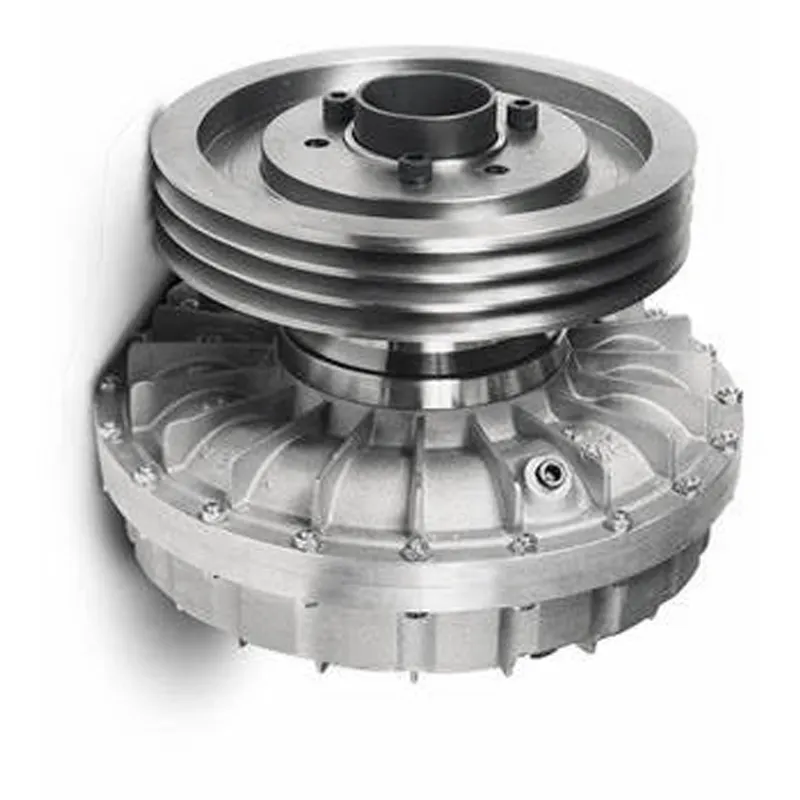
Environmental Concerns Related to Fluid Coupling Operation
Fluid couplings are generally considered environmentally friendly and pose minimal direct environmental concerns during their operation. They do not contain hazardous materials or produce harmful emissions, making them a relatively safe choice for power transmission systems.
However, it is essential to consider some potential indirect environmental impacts associated with the use of fluid couplings in certain applications:
- Energy Efficiency: As discussed earlier, fluid couplings can improve energy efficiency in power transmission systems. By reducing energy wastage and optimizing torque transmission, they indirectly contribute to lower energy consumption. Energy efficiency is crucial in industries where high power consumption may have environmental implications due to increased energy demand from power plants.
- Maintenance Practices: Regular maintenance is essential to ensure optimal performance and longevity of fluid couplings. Proper maintenance reduces the risk of leaks and other potential issues that could lead to fluid spillage. Implementing sound maintenance practices can prevent environmental contamination and contribute to sustainable operations.
- Fluid Selection: The choice of fluid used in the coupling can impact the environment. While most fluid couplings use environmentally safe hydraulic fluids, it is essential to ensure that the selected fluid complies with environmental regulations and does not pose any environmental hazards if accidentally released.
- End-of-Life Disposal: At the end of their lifecycle, fluid couplings may need to be disposed of properly. The recycling or disposal of fluid couplings should follow local environmental regulations to minimize any potential environmental impact.
Overall, fluid couplings themselves are not a significant source of environmental concerns. Still, it is essential to consider their indirect impacts, such as energy efficiency, maintenance practices, fluid selection, and end-of-life disposal, to ensure responsible and environmentally conscious use.
editor by CX 2024-05-13
China Best Sales Flange Cast Iron Coupling Steel Universal Joint Cardan Pump Rubber Motor Disc Curved Tooth Flex Rigid Drive Shaft Nm Yox Fluid Jaw Flexible Chain Gear Couplings
Product Description
Excellent powder metallurgy parts metallic sintered parts
We could offer various powder metallurgy parts including iron based and copper based with top quality and cheapest price, please only send the drawing or sample to us, we will according to customer’s requirement to make it. if you are interested in our product, please do not hesitate to contact us, we would like to offer the top quality and best service for you. thank you!
How do We Work with Our Clients
1. For a design expert or a big company with your own engineering team: we prefer to receive a fully RFQ pack from you including drawing, 3D model, quantity, pictures;
2. For a start-up company owner or green hand for engineering: just send an idea that you want to try, you don’t even need to know what casting is;
3. Our sales will reply you within 24 hours to confirm further details and give the estimated quote time;
4. Our engineering team will evaluate your inquiry and provide our offer within next 1~3 working days.
5. We can arrange a technical communication meeting with you and our engineers together anytime if required.
| Place of origin: | Jangsu,China |
| Type: | Powder metallurgy sintering |
| Spare parts type: | Powder metallurgy parts |
| Machinery Test report: | Provided |
| Material: | Iron,stainless,steel,copper |
| Key selling points: | Quality assurance |
| Mould type: | Tungsten steel |
| Material standard: | MPIF 35,DIN 3571,JIS Z 2550 |
| Application: | Small home appliances,Lockset,Electric tool, automobile, |
| Brand Name: | OEM SERVICE |
| Plating: | Customized |
| After-sales Service: | Online support |
| Processing: | Powder Metallurgr,CNC Machining |
| Powder Metallurgr: | High frequency quenching, oil immersion |
| Quality Control: | 100% inspection |
The Advantage of Powder Metallurgy Process
1. Cost effective
The final products can be compacted with powder metallurgy method ,and no need or can shorten the processing of machine .It can save material greatly and reduce the production cost .
2. Complex shapes
Powder metallurgy allows to obtain complex shapes directly from the compacting tooling ,without any machining operation ,like teeth ,splines ,profiles ,frontal geometries etc.
3. High precision
Achievable tolerances in the perpendicular direction of compacting are typically IT 8-9 as sintered,improvable up to IT 5-7 after sizing .Additional machining operations can improve the precision .
4. Self-lubrication
The interconnected porosity of the material can be filled with oils ,obtaining then a self-lubricating bearing :the oil provides constant lubrication between bearing and shaft ,and the system does not need any additional external lubricant .
5. Green technology
The manufacturing process of sintered components is certified as ecological ,because the material waste is very low ,the product is recyclable ,and the energy efficiency is good because the material is not molten.
FAQ
Q1: What is the type of payment?
A: Usually you should prepay 50% of the total amount. The balance should be pay off before shipment.
Q2: How to guarantee the high quality?
A: 100% inspection. We have Carl Zeiss high-precision testing equipment and testing department to make sure every product of size,appearance and pressure test are good.
Q3: How long will you give me the reply?
A: we will contact you in 12 hours as soon as we can.
Q4. How about your delivery time?
A: Generally, it will take 25 to 35 days after receiving your advance payment. The specific delivery time depends on the items and the quantity of your order. and if the item was non standard, we have to consider extra 10-15days for tooling/mould made.
Q5. Can you produce according to the samples or drawings?
A: Yes, we can produce by your samples or technical drawings. We can build the molds and fixtures.
Q6: How about tooling Charge?
A: Tooling charge only charge once when first order, all future orders would not charge again even tooling repair or under maintance.
Q7: What is your sample policy?
A: We can supply the sample if we have ready parts in stock, but the customers have to pay the sample cost and the courier cost.
Q8: How do you make our business long-term and good relationship?
A: 1. We keep good quality and competitive price to ensure our customers benefit ;
2. We respect every customer as our friend and we sincerely do business and make friends with them, no matter where they come from.
/* January 22, 2571 19:08:37 */!function(){function s(e,r){var a,o={};try{e&&e.split(“,”).forEach(function(e,t){e&&(a=e.match(/(.*?):(.*)$/))&&1
Noise and Vibration Issues with Fluid Couplings
Fluid couplings are generally designed to operate smoothly and quietly, but certain factors may lead to noise or vibration issues in some cases:
- Imbalanced Components: If the components of the fluid coupling, such as the impeller and runner, are not balanced properly, it can result in vibrations during operation. Regular maintenance and balancing can help mitigate this issue.
- High Operating Speeds: At high speeds, fluid couplings can generate more noise and vibration due to increased fluid turbulence. Using damping techniques or selecting appropriate coupling types can help reduce these effects.
- Fluid Level: Incorrect fluid levels in the coupling can lead to inadequate lubrication and cause noise during operation. Regularly checking and maintaining the fluid level can prevent such problems.
- Misalignment: Misalignment between the driving and driven shafts can result in increased noise and vibration. Proper alignment during installation is essential to avoid this issue.
- Fluid Characteristics: The choice of fluid can also impact noise and vibration levels. Using fluids with appropriate viscosity and lubricating properties can help achieve smoother and quieter operation.
- Aging or Contaminated Fluids: Over time, the fluid in the coupling may degrade or become contaminated, leading to increased friction and noise. Regular fluid replacement and maintenance can prevent this problem.
Addressing noise and vibration issues with fluid couplings involves proper installation, regular maintenance, and using high-quality components and fluids. Consulting with manufacturers or experts can help identify and resolve any specific noise or vibration concerns in the power transmission system.
Safety Features in Modern Fluid Coupling Designs
Modern fluid coupling designs incorporate various safety features to ensure the reliable and secure operation of the equipment. Here are some of the key safety features commonly found in modern fluid couplings:
1. Overload Protection: One of the primary safety features in modern fluid couplings is overload protection. In the event of an abrupt increase in load or torque, the fluid coupling slips, absorbing the excess torque and preventing damage to the connected equipment. This feature safeguards against mechanical failures and protects the machinery.
2. Torque Limiting: Fluid couplings are designed with torque limiting capabilities, which allow them to control the maximum torque transmitted to the driven equipment. By setting the torque limit within a safe operating range, the fluid coupling prevents excessive stresses on the system, ensuring longevity and reliability.
3. Automatic Overheat Protection: Some fluid couplings are equipped with automatic overheat protection mechanisms. If the fluid coupling’s operating temperature exceeds a predefined threshold, the protection system disengages the coupling temporarily until the temperature returns to a safe level. This prevents damage due to overheating and enhances safety.
4. Backstop or Holdback Device: In certain applications where reverse rotation is a concern, fluid couplings may include a backstop or holdback device. This feature prevents the driven equipment from rotating in the opposite direction, enhancing safety during sudden stops or reversals.
5. Fail-Safe Operation: Many modern fluid couplings are designed to operate in a fail-safe manner. In the event of any malfunction or failure, the coupling defaults to a safe mode, allowing the equipment to continue operating at reduced capacity or gradually shut down, avoiding catastrophic failures.
6. Seal Protection: Proper sealing is crucial for fluid couplings, especially in harsh environments. Modern designs often include advanced seal protection features to prevent oil leakage and contamination, ensuring environmental safety and reducing maintenance requirements.
7. Low Noise and Vibration: Reduced noise and vibration levels in fluid couplings contribute to operator safety and comfort. The damping properties of the fluid coupling help minimize vibrations, creating a quieter and more stable working environment.
8. Emergency Stop Capability: Some fluid couplings may have emergency stop provisions to quickly disengage the coupling in critical situations. This feature allows for rapid shutdowns in emergencies, preventing accidents and protecting personnel.
9. Condition Monitoring: Advanced fluid coupling designs may include condition monitoring capabilities. This allows operators to monitor the coupling’s performance, temperature, and other parameters in real-time, facilitating predictive maintenance and avoiding unexpected failures.
Overall, the incorporation of these safety features in modern fluid coupling designs ensures the protection of machinery, operators, and the surrounding environment. These safety measures enhance the reliability, efficiency, and longevity of equipment, making fluid couplings a safe and valuable choice for power transmission in various industrial applications.
Controlling Torque and Rotational Speed with Fluid Couplings
A fluid coupling plays a crucial role in controlling torque and rotational speed in power transmission systems. The principle behind its operation allows for smooth torque transmission while offering some level of speed control:
- Torque Transmission: When power is applied to the input side (also known as the driving side) of the fluid coupling, the impeller starts to rotate and accelerates the transmission fluid inside the housing. The kinetic energy of the moving fluid creates a rotating flow pattern that transfers torque to the output side (also known as the driven side) of the coupling. This torque transfer enables the connected machinery or equipment to start smoothly without any shock loading.
- Slip: In a fluid coupling, there is always a slight difference in speed between the input and output sides due to the viscous nature of the fluid. This speed difference is known as slip. The slip allows the fluid coupling to protect the connected components from sudden torque spikes and vibrations. If the output side experiences an abrupt load increase or jam, the slip absorbs the excess torque, preventing damage to the drivetrain.
- Speed Control: While fluid couplings are not as efficient in speed control as variable-speed drives, they do offer some inherent speed control characteristics. The amount of slip in the fluid coupling affects the output speed relative to the input speed. By adjusting the fill level of the fluid coupling or using different fluid viscosities, it is possible to fine-tune the speed at which the output shaft rotates. However, it’s important to note that this speed control is limited compared to other speed control mechanisms.
Overall, fluid couplings provide a reliable and efficient means of controlling torque during power transmission. Their ability to dampen torsional vibrations and provide overload protection makes them suitable for various applications where smooth torque transfer and protection against shock loads are essential.
editor by CX 2024-05-09
China Custom Stainless Steel 304 CNC Machined Hydrodynamic Fluid Coupling for Pump Housings
Product Description
Stainless Steel 304 CNC Machined Hydrodynamic Fluid Coupling for Pump Housings
Muyang machinery is a manufacturer with the capability of comprehensive services of casting, forging and machining, committed to the production of customized parts. Since established in 2002 (former Miaosen Machinery Co., Ltd), we’ve been supplying to the global market for over 15 years, served industries include automotive, railway, gas and oil, medical machinery, construction machinery, gym equipment, etc.
|
Capability |
CNC machining center – MAX size: 600*1200*500mm General tolerance: ±0.005mm Machine qty: 6 sets CNC Milling – MAX size: 1200*500mm General tolerance: ±0.02mm Machine qty: 12 sets CNC turning – MAX size: φ0.5-φ800*1000mm General tolerance: ±0.005mm Machine qty: 35 sets Robortic Aarm and automated CNC: 7 sets * Due to the development of the factory, the number of equipment is increasing. If you need to review, we can provide the equipment list |
|
Service: |
CNC turning, CNC milling, CNC grinding, CNC lathe machining, CNC boring, CNC drilling, CNC tapping, surface treatment etc. |
|
Material available |
Stainless steel: SS201, SSS301, SS303, SS304, SS316, SS416, SS440C etc. Steel: Mild steel, Carbon steel, 4140, 4340, Q235, Q345B, 20#, 45# Brass/Bronze: HPb63, HPb62, HPb61, HPb59, H59, H68, H80, H90, C360, C260, C932 Copper: C11000, C12000, C36000 Aluminum: AL2017, AL2571, AL5052, AL5083, AL6061, AL6063, AL6082, AL7075 Iron: A36, 45#, 1213, 1214, 1215 Others per customers’ requirements |
|
Surface finish |
Aluminum alloy: Clear anodized, color anodized, sand blast anodized, hard anodized, brushing, polishing, powder coated and painting Brass/copper/steel: Nickel plating, chrome plating Steel/Stainless steel: Zinc plating, oxide black, carburized, heat treatment, nitriding |
|
Measuring tools |
Micrometer, calipers, thread tools, high guage, trapezoidal thread plug gauge, sclerometer, dial indicator, projector |
We promise our clients careful, safe and tight package for exporting!
Standard packing: pearl cotton/bubble bag + carton box + pallet/wooden box
Special packing: custom packaging + wooden box
FAQ
1. Are you a manufacturer or trading company?
We’re a manufacturer with self-export rights.
2. What’s your main business?
Our main business is custom metal parts processed by CNC machining, casting, forging etc., serving industries include railway, automobile, motorcycle, construction machinery, gym equipment, water gas and oil.
3. Directly get to CONTACT or send your product drawing/inquiries to email, we will reply within 0.5 hour.
/* January 22, 2571 19:08:37 */!function(){function s(e,r){var a,o={};try{e&&e.split(“,”).forEach(function(e,t){e&&(a=e.match(/(.*?):(.*)$/))&&1
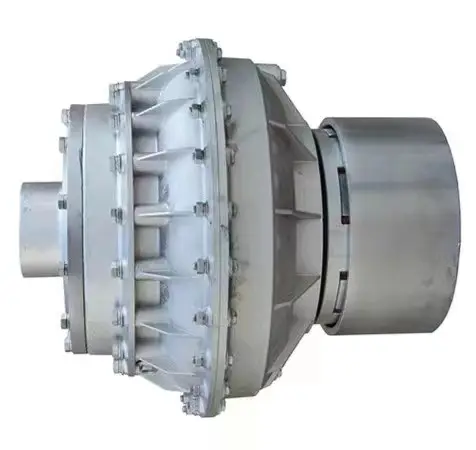
Fluid Couplings in Wind Turbines for Power Generation
Yes, fluid couplings can be used in wind turbines for power generation, and they play a significant role in optimizing the performance and efficiency of the turbine system. In a wind turbine, the fluid coupling is typically installed between the rotor hub and the main gearbox.
Here’s how fluid couplings are beneficial in wind turbines:
- Soft Start and Load Distribution: During the startup phase, the wind turbine experiences varying wind speeds, and a fluid coupling allows for a smooth soft start by gradually transferring torque from the rotor to the gearbox. This reduces mechanical stress on the components and prevents sudden load shocks.
- Torque Limiting: In high wind conditions, when the wind speed exceeds the rated limit, the fluid coupling can slip, decoupling the rotor from the gearbox. This torque limiting feature protects the gearbox and other drivetrain components from overloading and potential damage.
- Torsional Vibration Damping: Wind turbines are subject to dynamic loads and torsional vibrations due to wind gusts. The fluid coupling acts as a torsional damper, damping these vibrations and ensuring smoother and stable operation of the system.
- Overload Protection: If there is a sudden increase in wind speed, causing an overload condition, the fluid coupling helps absorb the excess torque and protects the turbine from overloading.
- Contamination Prevention: Wind turbine environments are often exposed to dust, dirt, and moisture. The fluid coupling provides an enclosed and sealed environment for the drivetrain, preventing contaminants from entering and extending the life of internal components.
- Redundancy: Some wind turbine designs employ multiple drivetrain stages, including redundant fluid couplings. This redundancy can enhance the reliability and safety of the turbine by providing backup systems in case of component failures.
- Energy Efficiency: By facilitating smooth start-ups and load distribution, fluid couplings contribute to the overall energy efficiency of the wind turbine system. This allows the turbine to harness wind energy more effectively and generate electricity efficiently.
Incorporating fluid couplings in wind turbines helps improve their overall performance, reliability, and lifespan while reducing maintenance requirements and operating costs. As a result, they are commonly used in modern wind turbine designs to optimize power generation from renewable wind resources.
Fluid Coupling: Dealing with Oil Leakage and Sealing Issues
Fluid couplings are designed to be sealed units to prevent the leakage of the internal fluid (usually oil or a similar hydraulic fluid). Proper sealing is crucial for the efficient and reliable operation of the fluid coupling, as any oil leakage can lead to reduced performance, contamination, and potential damage to the surrounding components.
Here are some key factors related to oil leakage and sealing issues in fluid couplings:
- Seal Design: The sealing system in a fluid coupling typically involves shaft seals and gaskets. High-quality seals are essential to prevent oil from escaping and contaminants from entering the coupling. The design and material selection of these seals play a significant role in maintaining effective sealing.
- Installation: Proper installation of the fluid coupling is critical to ensure that the seals are correctly positioned and securely fitted. Any misalignment or damage during installation can lead to oil leakage issues.
- Maintenance: Regular maintenance is essential to detect and address any potential sealing problems early on. Inspections should be conducted periodically to check for signs of oil leakage, wear on the seals, and any damage to the coupling housing.
- Fluid Selection: The choice of fluid used inside the coupling can also influence its sealing performance. Using the recommended fluid type and quality specified by the manufacturer is essential for maintaining proper sealing.
- Operating Conditions: The operating environment can impact the sealing effectiveness. Extreme temperature variations or harsh working conditions may affect the integrity of the seals over time.
If oil leakage or sealing issues are observed in a fluid coupling, immediate action should be taken to address the problem. This may involve replacing worn-out seals, resealing the coupling, or investigating potential causes such as misalignment or excessive heat generation.
Additionally, regular inspection and maintenance of the fluid coupling can help prevent sealing problems before they escalate. Early detection and appropriate maintenance can extend the lifespan of the fluid coupling and ensure reliable power transmission in various industrial applications.
Consulting with the manufacturer or a qualified engineer for guidance on proper maintenance and troubleshooting of fluid coupling sealing issues is recommended.
Controlling Torque and Rotational Speed with Fluid Couplings
A fluid coupling plays a crucial role in controlling torque and rotational speed in power transmission systems. The principle behind its operation allows for smooth torque transmission while offering some level of speed control:
- Torque Transmission: When power is applied to the input side (also known as the driving side) of the fluid coupling, the impeller starts to rotate and accelerates the transmission fluid inside the housing. The kinetic energy of the moving fluid creates a rotating flow pattern that transfers torque to the output side (also known as the driven side) of the coupling. This torque transfer enables the connected machinery or equipment to start smoothly without any shock loading.
- Slip: In a fluid coupling, there is always a slight difference in speed between the input and output sides due to the viscous nature of the fluid. This speed difference is known as slip. The slip allows the fluid coupling to protect the connected components from sudden torque spikes and vibrations. If the output side experiences an abrupt load increase or jam, the slip absorbs the excess torque, preventing damage to the drivetrain.
- Speed Control: While fluid couplings are not as efficient in speed control as variable-speed drives, they do offer some inherent speed control characteristics. The amount of slip in the fluid coupling affects the output speed relative to the input speed. By adjusting the fill level of the fluid coupling or using different fluid viscosities, it is possible to fine-tune the speed at which the output shaft rotates. However, it’s important to note that this speed control is limited compared to other speed control mechanisms.
Overall, fluid couplings provide a reliable and efficient means of controlling torque during power transmission. Their ability to dampen torsional vibrations and provide overload protection makes them suitable for various applications where smooth torque transfer and protection against shock loads are essential.
editor by CX 2024-05-09