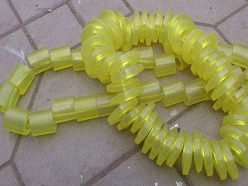
 Elastic sleeveThe elastic sleeve uses a number of non-metal elastic...
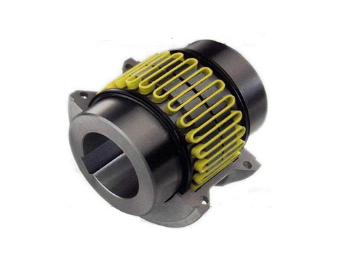 JSZ type brake wheel couplingThe structure of JSZ type brake wheel coupling...
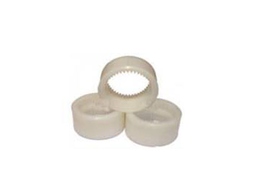 Nylon sleeve inner gear ringThe main purpose of the nylon sleeve inner gear ring is:...
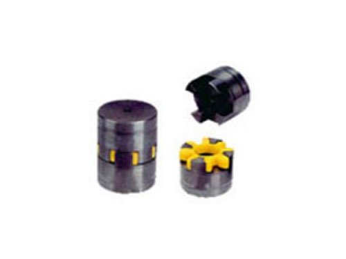 LXD type single flange star elastic couplingLXD type single flange star elastic coupling is...
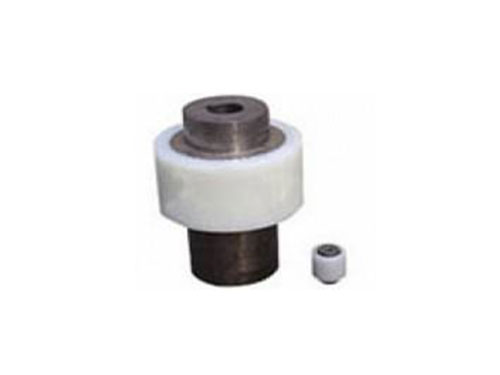 NL type drum gear couplingThe shaft hole types are cylindrical (Y), conical...
Compensation type and alignment method of diaphragm coupling
The forms of misalignment that the diaphragm coupling can compensate include the following three basic types: angular (the center lines of the two shafts intersect at the midpoint between the ends of the two shafts at an angle), transverse (the center lines of the two shafts are offset in parallel) and Axial (the axial gap between the two shafts is too large).The actual offset that occurs during the operation of the rotating shaft system is often a combination of any of the above two types of misalignment or three types of misalignment at the same time, so the load and deformation of the diaphragm coupling during actual work are more complicated.
The membrane segment between two adjacent bolt holes can be equivalent to a cantilever beam, and the material mechanics method is used to deduce that the connecting rod diaphragm coupling can bear torque, centrifugal load, axial offset, and angular deviation. The calculation formula for the internal stress of the diaphragm is shifted, and a method for calculating the torsional stiffness of the diaphragm is proposed. It is a typical method to analyze the stress and stiffness of the diaphragm by using empirical formulas. However, its major disadvantage is that the area around the bolt hole cannot be considered The influence of the stress concentration effect causes a large gap between the calculated stress and the actual stress.
We conducted discussions on these two points, taking the waist-type elastic diaphragm coupling that is common in engineering applications as an example, using the finite element software ANSYS to model, and introducing the transient dynamics analysis method into the stress analysis of the diaphragm coupling .The transient dynamics method is a method used to determine the dynamic response of a structure subject to any time-varying load. It can be analyzed to determine the structure's change with time under any combination of static load, transient load and simple harmonic load. Displacement, strain, stress and force.
As the key elastic element of the diaphragm coupling, the diaphragm bears the main load during operation.
When the diaphragm coupling rotates, its angular deviation will produce alternating stress, which alternates once per rotation.The dynamic stress of the diaphragm will cause the fatigue damage of the diaphragm and the bolt, so the accurate calculation of the dynamic and static composite stress is the key to predicting the life of the diaphragm coupling and determining the work of the diaphragm coupling.
The existing related researches are mostly limited to the analysis of the stress distribution of the diaphragm when it is subjected to a certain load, and the dynamic and static composite stress when the diaphragm is actually subjected to a complex load is rarely involved.
The diaphragm coupling relies on the elastic deformation of the diaphragm to compensate for the relative displacement of the two shafts connected. It is a flexible coupling with strong metal components. It does not require lubrication, has a compact structure, good service life, no rotation, and no Affected by temperature and oil pollution, it is suitable for shafting transmission in high temperature and corrosive environment.Special attention should be paid to this key problem of left and right, so everyone should pay special attention to this kind of problem when using and installing and disassembling. It can increase the life of the coupling and prevent it from being more serious. The common faults and damages can make the actual effect of the diaphragm coupling more complete, and can also prevent the damage to its full normal function.If an error occurs, the active end or the driven end need to be re-aligned.First find out the part with large offset error, this must first measure which side of the coupling is offset, that is, measure the level and coaxiality of the main shaft and the level and coaxiality of the reducer main shaft, and re-copy according to the quality scale. The fault can be removed by leveling and aligning.
Alignment and device method of diaphragm coupling
【1】Bolt for device: Insert the bolt from the outside of the small hole of the flange, pass it through the outside of the large hole of the other flange, put on the buffer sleeve, elastic washer, twist the nut, and tighten the nut with a wrench.If the device is unsuitable or dismantled and replaced, without damaging the shaft and half coupling, it is better to rotate freely after the installation.
[2] First check whether the work is in place. Before installation, check whether the prime mover and the working machine are not concentric, whether there are wrapping paper and bumps on the surface of the two shafts, and the plum blossom coupling is in the two half couplings. Whether there is debris in the hole, whether there are bruises on the edge of the inner hole, if any, the shaft and half coupling should be cleaned up, and the bruises should be treated with a fine file.Then check whether the inner hole diameter and length of the two half couplings are consistent with the diameter and shaft elongation of the prime mover and working machine.In general selection, it is better to let the length of the prime mover and the working machine end half coupling be less than 10-30mm of shaft elongation.
【3】找正:用百分表检测两半联轴节法兰盘端面和外圆跳动,当法兰盘外圆小于250mm时跳动值应不大于0.05mm;当法兰盘外圆大于250mm时,跳动值应不大于0.08。
[4] Secondly, in order to facilitate the installation, it is better to put the two half couplings in the 120-150 incubator or oil tank for preheating in advance, so that the size of the inner hole is enlarged and it is easy to install.After the device, the shaft head cannot protrude from the end surface of the half coupling, and it is better to be flush.Detect the distance between the two halves of the coupling: take the average of the readings of 3-4 points measured along the two inner sides of the flange of the half coupling, and the sum of the measured dimensions of the extension and the two diaphragm groups. The error is controlled within the range of 0-0.4mm.