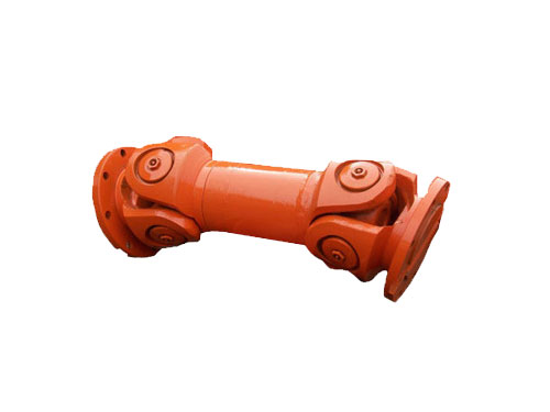
 Universal couplingThe universal coupling uses the characteristics of its mechanism...
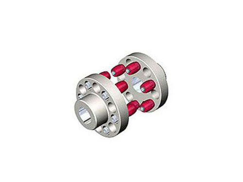 HL type elastic pin couplingThe elastic pin coupling (GB5014-85) is suitable for...
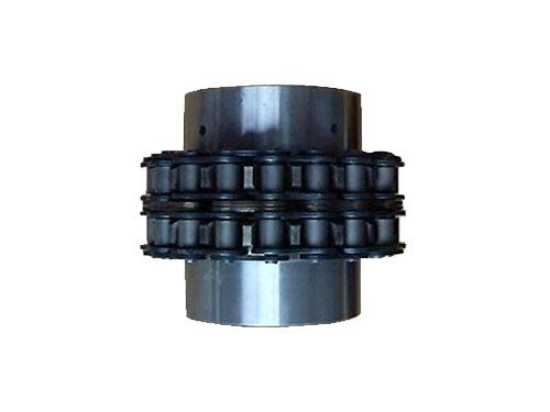 GLF roller chain couplingGLF roller chain coupling is suitable for hydraulic machinery...
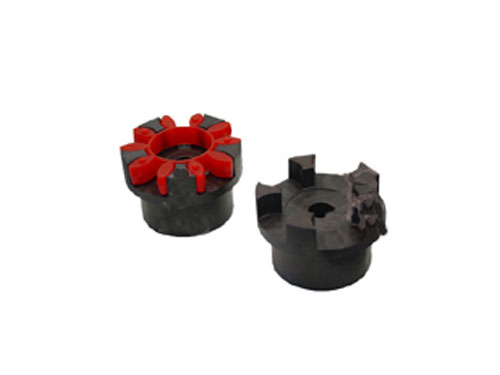 XL type star elastic couplingXL type star elastic coupling and other coupling...
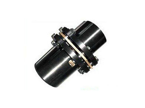 JMⅡ type non-counterbore basic diaphragm couplingJMⅡ type non-counterbore basic diaphragm coupling...
What you need to know when disassembling the plum blossom coupling
Before disassembling the plum blossom coupling, make some marks on the coordinated positions of the various parts of the coupling for reference when reassembling.For couplings used in high-speed machines, the connecting bolts are weighed, and the markings need to be clear and cannot be mistaken.
Cleaning, cleaning and quality evaluation of all parts of the plum blossom coupling is an important task after the coupling is disassembled.The evaluation of components refers to the comparison of the existing conditions of the size, shape and material properties of each component with the quality standards determined by the component design to determine which components can continue to be used and which components should be used. Which parts should be scrapped and used after repair?
The type of plum coupling should be determined according to the use requirements and working conditions.The following points can be considered when making specific choices:
[1] The performance and working environment of the coupling are usually made of metal components and do not require lubrication. Compared with couplings that require lubrication, their performance is easily affected by the degree of lubrication and may pollute the environment.
[2] The working speed of the coupling and the amount of centrifugal force caused by it, for the transmission shaft, a coupling with a high degree of balance should be selected.
[3] The size and direction of the relative displacement of the two shafts. After installation and adjustment, it is difficult to keep the two shafts in strict alignment, or when the two shafts produce a large additional relative displacement during the working process, a flexible coupling should be selected.
[4] For the manufacture, installation, maintenance and cost of the coupling, on the premise of achieving the use performance, a coupling that is convenient for assembly and disassembly, simple for maintenance, and reasonable cost should be selected.
[5] The size and nature of the torque to be transmitted and the requirements for cushioning and vibration reduction.
The stiffness of the coupling includes radial stiffness, axial stiffness and torsional stiffness.In actual engineering, the load changes are often caused by torsional vibration caused by torque fluctuations, so the main stiffness of the coupling is the torsional stiffness.In general, in shafting transmission, the stiffness of other parts of the system will be much larger than that of the elastic coupling. Therefore, in the simplified case, assuming that the elasticity of other parts is zero, only the coupling is considered.的flexibility.The torsional stiffness of the coupling is used as the torsional stiffness of the drive shaft system.
The allowable axis deviation of the coupling includes radial, angular and axial deviation.When installing, please adjust the axis deviation within the allowable range of the corresponding product catalog.
[1] Installation of coupling mounting plate: The fit between the inner hole of the mounting plate and the journal is generally designed as a "transition fit" or "interference fit", so the inner hole of the mounting plate and the outer diameter of the shaft should be carefully checked before installation , The surface is clean and free of burrs.
[2] For straight shaft: Put the key into the key groove on the diaphragm coupling shaft, the key end should not be protruding or recessed into the shaft end, it is better to be flush.Put the mounting plate in the oil tank and heat it at a temperature of 120~150℃. After heating and keeping warm, the LLB type non-framework tire coupling is installed on the shaft according to the coupling installation diagram and pay attention to the position mark on the shaft. The disc and the shaft end should generally be flush.Partial heating is not allowed during heating to avoid deformation.
[3] For tapered shaft: Install the key on the shaft as required by the flat shaft key, then install the mounting plate on the shaft, push it tightly, and tighten it with a nut to move the mounting plate axially to Its fixed position.
[4] Detect the distance between the two shaft ends: first, the main and driven machine rotors should be placed in the running position, pay attention to the axial movement of the two machines, should be leaned against the working position, and then detect the diaphragm coupling The distance between the two shaft ends of the shaft device should be adjusted to the position specified on the general installation drawing.
[5] Unseal and clean the components of a complete set of couplings.
It is typically simplified to two equivalent discs, which are arranged on both sides of the coupling.During the work of the coupling, the cyclic load is a typical load form in mechanical transmission.In order to avoid resonance, the changing frequency of the periodic load and the natural frequency of the drive shaft should be staggered.The method is to change the change frequency of the periodic load or change the change frequency of the shaft system.Because the load change frequency is related to the spindle speed, and the speed is a mechanical performance parameter, generally it cannot be changed at will.Therefore, the purpose of not resonating is generally achieved by changing the natural frequency of the shafting system, and changing the natural frequency of the shafting system generally changes the moment of inertia or stiffness of the shafting system. The moment of inertia is related to the mechanical structure, and it is difficult to achieve by changing the moment of inertia. , And the stiffness of the shaft system is easy to change.Therefore, changing the elastic coupling is to change the stiffness of the shaft system to achieve the purpose of avoiding resonance.