Guangdong star elastic coupling
Guangdong elastic sleeve pin coupling
Guangdong diaphragm coupling series
Guangdong elastic pin coupling
Guangdong drum gear coupling series
Guangdong plum-shaped elastic coupling
Guangdong rigid coupling series
Guangdong tire coupling series
Guangdong Slider Coupling Series
Guangdong Universal Coupling Series
Guangdong roller chain coupling
Guangdong water pump coupling
Guangdong various coupling accessories
Guangdong Industrial Expansion Set
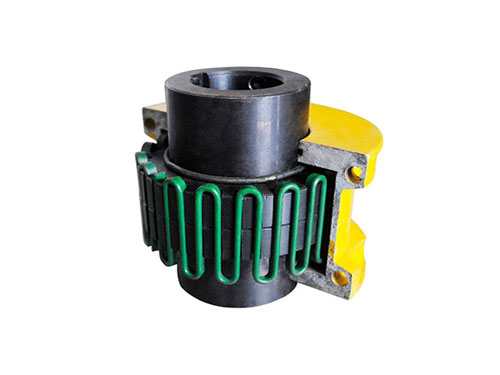
Guangdong serpentine spring coupling accessories
Guangdong reducer bracket series
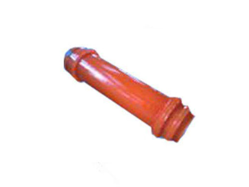 Guangdong WGT type connecting middle sleeve gear couplingWGT type connecting middle sleeve gear coupling is working...
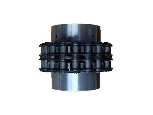 Guangdong GLF roller chain couplingGLF roller chain coupling is suitable for hydraulic machinery...
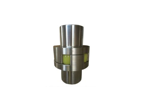 Guangdong ML plum blossom elastic couplingML plum-shaped elastic coupling and other coupling...
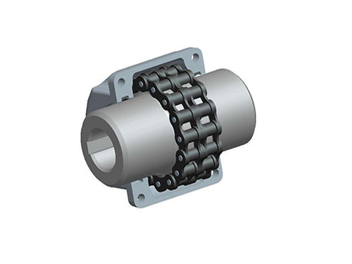
Guangdong GL type roller chain coupling

GL-type roller chain coupling AUTOCAD renderings (GB6069-2002 instead of GB6069-86) Features: The chain coupling uses a common chain and meshes with two parallel sprockets with the same number of teeth at the same time. Chain couplings of different structural types The main difference between the shafts is the use of different chains, the common ones are double-row roller chain couplings, single-row roller chain couplings, toothed chain couplings, nylon chain couplings, etc.The performance of double-row roller chain couplings is better than that of other structural types of couplings. It is widely used and our country has also formulated it as a standard.
Example 1: GL7 type roller coupling
主动端:J1型孔,B型键槽 d1=45mm,L1=84mm
从动端:J1型孔,B1型键槽 d2=50mm ,L1=84mm
GL7 coupling
J1B45×84/J1B150×84=GB6069-85
Example 2: GL3 type roller chain shaft with cover
主动端:J1型孔,B型键槽 d1=25mm,L1=44mm
从动端:J1型孔,B1型键槽 d2=25mm ,L1=44mm
G13F联轴器J125×44 GB6069-85
| model | Nominal torque TnN·m | Allowable speed (n) r / min | Diameter of shaft hole d1, d2 | Length of shaft hole | Chain number | Chain Pitch | Number of teeth Z | D | b1 | S | A | Dx ( Big) | Lx ( Big) | 质量 kg | Transmission inertia kg·m2 | ||
| Y type | J1 type | ||||||||||||||||
| Without cover | Install the cover | L | L1 | ||||||||||||||
| GL1 | 40 | 1400 | 4500 | 16 | 42 | - | 06B | 9.525 | 14 | 51.06 | 5.3 | 4.9 | - | 70 | 70 | 0.40 | 0.00010 |
| 18 | 42 | - | - | ||||||||||||||
| 19 | 42 | - | - | ||||||||||||||
| 20 | 52 | 38 | 4 | ||||||||||||||
| GL2 | 63 | 1250 | 4500 | 19 | 42 | - | 06B | 9.525 | 16 | 57.08 | 5.3 | 4.9 | - | 75 | 75 | 0.70 | 0.00020 |
| 20 | 52 | 38 | 4 | ||||||||||||||
| 22 | 52 | 38 | 4 | ||||||||||||||
| 24 | 52 | 38 | 4 | ||||||||||||||
| GL3 | 100 | 1000 | 4000 | 20 | 52 | 38 | 08B | 12.7 | 14 | 68.88 | 7.2 | 6.7 | 12 | 85 | 80 | 1.1 | 0.00038 |
| 22 | 52 | 38 | 12 | ||||||||||||||
| 24 | 52 | 44 | 12 | ||||||||||||||
| 25 | 62 | - | 6 | ||||||||||||||
| GL4 | 160 | 1000 | 4000 | 24 | 52 | - | 08B | 12.7 | 16 | 76.91 | 7.2 | 6.7 | - | 95 | 88 | 1.8 | 0.00086 |
| 25 | 62 | 44 | 6 | ||||||||||||||
| 28 | 62 | 44 | 6 | ||||||||||||||
| 30 | 82 | 60 | - | ||||||||||||||
| 32 | 82 | 60 | - | ||||||||||||||
| GL5 | 250 | 800 | 3150 | 28 | 62 | - | 10A | 15.875 | 16 | 94.46 | 8.9 | 9.2 | - | 112 | 100 | 3.2 | 0.0025 |
| 30 | 82 | 60 | - | ||||||||||||||
| 32 | 82 | 60 | - | ||||||||||||||
| 35 | 82 | 60 | - | ||||||||||||||
| 38 | 82 | 60 | - | ||||||||||||||
| 40 | 112 | 84 | - | ||||||||||||||
| GL6 | 400 | 630 | 2500 | 32 | 82 | 60 | 10A | 15.875 | 20 | 116.57 | 8.9 | 9.2 | - | 140 | 105 | 5.0 | 0.0058 |
| 35 | 82 | 60 | - | ||||||||||||||
| 38 | 82 | 60 | - | ||||||||||||||
| 40 | 112 | 84 | - | ||||||||||||||
| 42 | 112 | 84 | - | ||||||||||||||
| 45 | 112 | 84 | - | ||||||||||||||
| 18 | 112 | 84 | - | ||||||||||||||
| 50 | 112 | 84 | - | ||||||||||||||
| GL7 | 630 | 630 | 2500 | 40 | 112 | 60 | 12A | 19.05 | 18 | 127.78 | 11.9 | 10.9 | - | 150 | 122 | 7.4 | 0.012 |
| 42 | 112 | 60 | - | ||||||||||||||
| 45 | 112 | 60 | - | ||||||||||||||
| 48 | 112 | 84 | - | ||||||||||||||
| 50 | 112 | 84 | - | ||||||||||||||
| 55 | 112 | 84 | - | ||||||||||||||
| 60 | 142 | 107 | - | ||||||||||||||
| GL8 | 1000 | 500 | 2240 | 45 | 112 | 84 | 16A | 25.40 | 16 | 154.33 | 15.0 | 14.3 | 12 | 180 | 135 | 11.1 | 0.025 |
| 48 | 112 | 84 | 12 | ||||||||||||||
| 50 | 112 | 84 | 12 | ||||||||||||||
| 55 | 112 | 84 | 12 | ||||||||||||||
| 60 | 142 | 107 | - | ||||||||||||||
| 65 | 142 | 107 | - | ||||||||||||||
| 70 | 142 | 107 | - | ||||||||||||||
| GL9 | 1600 | 400 | 2000 | 50 | 112 | 84 | 16A | 25.4 | 20 | 186.50 | 15.0 | 14.3 | 12 | 215 | 145 | 20.0 | 0.061 |
| 55 | 112 | 84 | 12 | ||||||||||||||
| model | Nominal torque TnN·m | Allowable speed (n) r / min | Diameter of shaft hole d1, d2 | Length of shaft hole | Chain number | Chain Pitch | Number of teeth Z | D | b1 | S | A | Dx ( Big) | Lx ( Big) | 质量 kg | Transmission inertia kg·m2 | ||
| Y type | J1 type | ||||||||||||||||
| Without cover | Install the cover | L | L1 | ||||||||||||||
| GL9 | 1600 | 400 | 2000 | 60 | 142 | 107 | 16A | 25.40 | 20 | 186.50 | 15.0 | 14.3 | - | 215 | 145 | 20.0 | 0.061 |
| 65 | 142 | 107 | - | ||||||||||||||
| 70 | 142 | 107 | - | ||||||||||||||
| 75 | 142 | 107 | - | ||||||||||||||
| 80 | 172 | 132 | - | ||||||||||||||
| GL10 | 2500 | 315 | 1600 | 60 | 142 | 107 | 20A | 31.75 | 18 | 213.02 | 18.0 | 17.8 | 6 | 245 | 165 | 26.1 | 0.079 |
| 65 | 142 | 107 | 6 | ||||||||||||||
| 70 | 142 | 107 | 6 | ||||||||||||||
| 75 | 142 | 107 | 6 | ||||||||||||||
| 80 | 172 | 132 | - | ||||||||||||||
| 85 | 172 | 132 | - | ||||||||||||||
| 90 | 172 | 132 | - | ||||||||||||||
| GL11 | 4000 | 250 | 1500 | 75 | 142 | 107 | 24A | 38.1 | 16 | 231.49 | 24.0 | 21.5 | 35 | 270 | 195 | 39.2 | 0.188 |
| 80 | 172 | 132 | 10 | ||||||||||||||
| 85 | 172 | 132 | 10 | ||||||||||||||
| 90 | 172 | 132 | 10 | ||||||||||||||
| 95 | 212 | 132 | 10 | ||||||||||||||
| 100 | 172 | 167 | - | ||||||||||||||
| GL12 | 6300 | 250 | 1250 | 85 | 172 | 132 | 28A | 44.45 | 16 | 270.08 | 24.0 | 24.9 | 20 | 310 | 205 | 59.4 | 0.380 |
| 90 | 172 | 132 | 20 | ||||||||||||||
| 95 | 172 | 132 | 20 | ||||||||||||||
| 100 | 212 | 167 | - | ||||||||||||||
| 110 | 212 | 167 | - | ||||||||||||||
| 120 | 212 | 167 | - | ||||||||||||||
| GL13 | 10000 | 200 | 1120 | 100 | 212 | 167 | 32A | 50.8 | 18 | 340.80 | 30.0 | 28.6 | 14 | 380 | 230 | 86.5 | 0.869 |
| 110 | 212 | 167 | 14 | ||||||||||||||
| 120 | 212 | 167 | 14 | ||||||||||||||
| 125 | 212 | 167 | 14 | ||||||||||||||
| 130 | 252 | 202 | - | ||||||||||||||
| 140 | 252 | 202 | - | ||||||||||||||
| GL14 | 16000 | 200 | 1000 | 120 | 212 | 167 | 32A | 50.8 | 22 | 405.22 | 30.0 | 28.6 | 14 | 450 | 250 150.8 | 2.06 | |
| 125 | 212 | 167 | 14 | ||||||||||||||
| 130 | 252 | 202 | - | ||||||||||||||
| 140 | 252 | 202 | - | ||||||||||||||
| 150 | 252 | 202 | - | ||||||||||||||
| 160 | 302 | 202 | - | ||||||||||||||
| GL15 | 25000 | 200 | 900 | 140 | 252 | 202 | 40A | 63.5 | 20 | 466.25 | 36.0 | 35.6 | 18 | 510 | 285 | 234.4 | 4.37 |
| 150 | 252 | 202 | 18 | ||||||||||||||
| 160 | 302 | 242 | - | ||||||||||||||
| 170 | 302 | 242 | - | ||||||||||||||
| 180 | 302 | 242 | - | ||||||||||||||
| 190 | 352 | 282 | - | ||||||||||||||
Note:
1. When there is a cover, add "F" after the model number, for example, GL5 type coupling, when there is a cover, change to GL5F.
2. The coupling mass and moment of inertia in the table are approximate values.
3、联轴器的轴孔和键槽型式及尺寸见表4-2-3和表4-2-5。
4. The lubrication of the coupling has a significant impact on the performance. It should be lubricated regardless of whether there is an outer cover or not.
5. Refer to Table 4-2-10 for the allowable compensation amount of the coupling.
Table 4-2-10 Allowable compensation of roller coupling
| model | GL1 | GL2 | GL3 | GL4 | GL5 | GL6 | GL7 | GL8 | GL9 | GL10 | GL11 | GL12 | GL13 | GL14 | GL15 |
| Project | |||||||||||||||
| Radial △Y, mm | 0.19 | 0.19 | 0.25 | 0.25 | 0.32 | 0.32 | 0.38 | 0.50 | 0.50 | 0.63 | 0.76 | 0.88 | 1.0 | 1.0 | 1.27 |
| Axial △X, mm | 1.4 | 1.4 | 1.9 | 1.9 | 2.3 | 2.3 | 2.8 | 3.8 | 3.8 | 4.7 | 5.7 | 6.6 | 7.6 | 7.6 | 9.5 |
| Angular △α | 1 ° | ||||||||||||||

 Guangdong JSB type axial mounting coupling
J-type axial mounting coupling is generally...
Guangdong JSB type axial mounting coupling
J-type axial mounting coupling is generally...
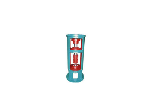 Guangdong XS type double fulcrum rack
Arrangement in the XS type double pivot rack...
Guangdong ML plum blossom elastic coupling
ML plum-shaped elastic coupling and...
Guangdong XS type double fulcrum rack
Arrangement in the XS type double pivot rack...
Guangdong ML plum blossom elastic coupling
ML plum-shaped elastic coupling and...
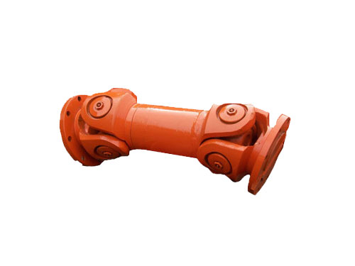 Guangdong Universal Coupling
The universal coupling uses its mechanism...
Guangdong Universal Coupling
The universal coupling uses its mechanism...