 LMZ-ⅡPlum-shaped elastic coupling with brake wheelLMZ-Ⅱ (formerly MLL-Ⅱ) type with brake wheel plum...
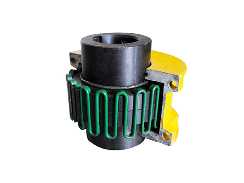 JSB type axial mounting couplingThe general material of J-type axial installation coupling...
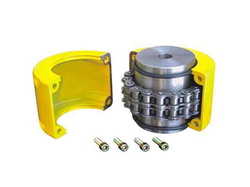 Roller chain couplingRoller chain couplings can be used in textiles, agriculture...
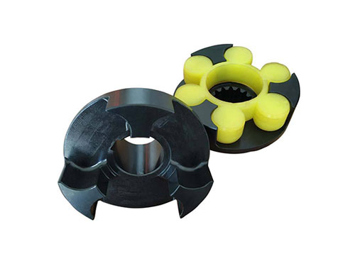
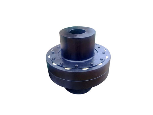 HL nylon rod pin couplingHL nylon rod pin coupling has good toughness...
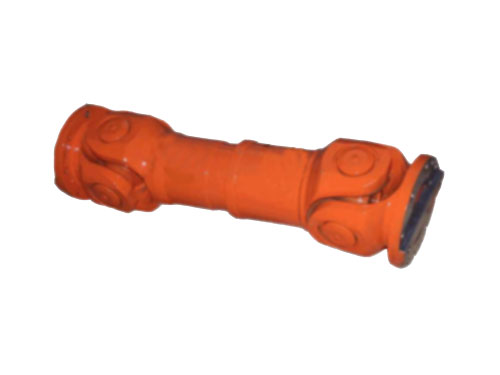 WF type non-telescopic flange universal couplingUniversal coupling is a kind of coupling,...
Compensation ability and selection steps of diaphragm coupling
The diaphragm coupling has no need for lubrication, good service life, and large compensation capabilities.Torque is transmitted through the flexible steel sheet, which has angular, axial and radial displacement compensation capabilities and shock absorption.The diaphragm is easy to assemble and disassemble, without lubrication, and can be ideally applied to various working conditions.
Diaphragm couplings are favored by construction machinery and rolling machinery because of their excellent performance. Although diaphragm couplings can fail or even be scrapped due to various reasons, their failure causes are of great significance.Diaphragm damage is the main form of coupling failure, and the damaged diaphragm ring is called.The failure analysis method is a common and practical system in engineering.The analysis method is simple, intuitive, and flexible, and is suitable for failure analysis of diaphragm couplings.The author will use this analysis method to analyze the failure mechanism of the diaphragm coupling according to the specific failure mode of the diaphragm coupling in the engineering practice.
[1] Misaligned installation.The misalignment of the bearings on both sides of the coupling and the two ends of the system has a great influence on the static characteristics of the system support. The misalignment makes the vibration isolation effect of the diaphragm coupling worse, and the misalignment makes the stability of the system tend to be , Which in turn affects the service life of the diaphragm coupling.Therefore, it is necessary to align the diaphragm coupling before installing. There are three common alignment methods: the single meter method is suitable for the relative position of each axis in a cold state, and the distance between the two halves of the coupling is long, Alignment of the unit with a small coupling diameter; the double-meter method is suitable for the alignment of the mechanical equipment when the shafts of the mechanical equipment are in a horizontal state. At this time, it is more convenient to use the double-meter method to align, but pay attention to the alignment process Make the shaft close to one end, and the axial movement will affect the alignment reading. In the installation of general-purpose pumps, fans and other equipment, we often use the double-meter method for alignment; the three-meter method Alignment is suitable for the alignment of multi-stage units and the cold state of each shaft is in a horizontal position. The three-meter method can be used to affect the relative movement of the two shafts, and a relatively good alignment accuracy can be obtained.This method is used in the alignment of reciprocating compressor units and large centrifugal units with low rotation belts.
【2】The diaphragm is damaged.The diaphragm is the key element of the diaphragm flexible coupling. Due to the offset between the axes, the transmission of torque, and the bearing of centrifugal force, the diaphragm is in a complex state of stress during operation.Its fatigue life determines the normal service life of the diaphragm coupling.Tensile fracture at the ends of the connecting holes at both ends and instability bending deformation of the diaphragm under pressure are common manifestations of diaphragm damage, so the probability of failure has a great influence on the overall failure probability of the diaphragm coupling, so in engineering practice We need to check and repair the diaphragm regularly to ensure its stable transmission performance.The waist-shaped diaphragm has the correct shape and low stress level. Under the same parameters, the calculated life is much longer than that of the annular diaphragm, and the additional load caused on the coupling is small, so the waist-shaped diaphragm can be used Piece coupling.The properly designed diaphragm structure and the number of laminated layers make the diaphragm coupling have a longer service life and meet the requirements of no damage during the overhaul of the unit.
[3] Bolt damage and deflection.The undercut groove at the bolt root causes stress concentration due to poor processing quality, and there are inclusions in the material, and there is a problem with the installation of the laminated diaphragm coupling and other parts of the unit (such as fan blades and gearbox) are also damaged, etc. Due to the existence of various factors, the laminated diaphragm coupling bolt set is used in the working condition of frequent start and large load. Once the working stress exceeds the working stress that the bolt can withstand, it will cause fatigue and fracture, which will eventually lead to the laminated diaphragm. The coupling is damaged.Measures are as follows: ①When designing laminated diaphragm couplings, sufficient attention should be paid to the processing quality of bolt undercut grooves, and the metallurgical quality and heat treatment process of bolt materials should be strictly controlled to improve the fatigue strength of bolts; ②Laminated diaphragm The installation of the coupling must strictly control the installation accuracy, reduce the angular deviation, radial deviation and axial compression or tension between the two halves of the coupling, strictly control the dynamic balance accuracy of the coupling, and reduce vibration. In order to reduce the alternating cyclic stress of the bolt group, it is necessary to control the pre-tightening force of the installation bolt within the specified range; ③At the coupling work site, it is necessary to install a vibration monitoring device to give an alarm in time when abnormality occurs to avoid short-term overload. The prevention ratio hazard is further expanded.
In terms of processing technology, fine blanking, laser cutting, and various high-precision machining centers have been applied to the production of diaphragm coupling parts, and there is no big difference between the machining accuracy and surface condition of the parts and the product.In short, the design performance and processing level of domestic diaphragm couplings are comparable to those of enterprises, and various grades of diaphragm couplings that meet the standards can be designed and manufactured.
However, domestic users often have concerns about choosing domestic diaphragm couplings, especially large turbo-compressor units.They are mainly worried about the following 3 aspects:
【1】I am worried that domestic materials will not pass the test.
[2] Worried about the lack of application performance of domestic diaphragm couplings.
[3] Worried that the design and manufacture of domestic diaphragm couplings will not pass.
Selection steps and methods of diaphragm couplings.
【1】Select the variety and type of diaphragm coupling.Understand the comprehensive function of the coupling in the transmission system, and choose the variety and type of the coupling from the overall design of the transmission system.According to the prime mover category and working load category, working speed, transmission accuracy, two-axis offset conditions, temperature, humidity, working environment and other comprehensive factors to select the type of coupling.Select the structure of the coupling according to the needs of the supporting host. When the coupling is used in conjunction with the brake, the coupling with brake wheel or brake disc should be selected; when overload protection is required, the coupling should be selected; When connecting with flanges, the flange type should be selected; for long-distance transmission, when the axial size of the connection is large, the intermediate shaft type or the intermediate sleeve type should be selected.
[2] Select the type, type and specification of the coupling.According to the comprehensive factors such as power machine and coupling load category, speed, working environment, etc., select the type of coupling; select the coupling type according to the matching of the coupling and connection conditions; according to the nominal torque and shaft hole diameter Select specifications with the length of the shaft hole.For the strength of the shaft and key, after the coupling model is selected, the strength of the shaft and key should be checked, and the coupling model should be determined later.
【3】Select standard diaphragm coupling.When choosing a coupling, the designer should first choose from the standards, machinery industry standards, and couplings that have been formulated. Only when the existing standard couplings and couplings cannot meet the design needs, do they need to design the coupling by themselves .
【4】Select the connection type.The choice of coupling connection type depends on the connection type of the main and driven ends to the shaft. Generally, a key connection is adopted, which is a unified key connection type and code. There are seven keyway types and four keyless connections specified in GB/T3852. , The most used is the A-type key.
[5] Adjust the model according to the shaft diameter.The preliminarily selected coupling dimensions of the diaphragm coupling, namely the shaft hole diameter d and the shaft hole length L, should meet the requirements of the shaft diameter of the driving and driven ends, otherwise the coupling specifications must be adjusted according to the shaft diameter d.It is a common phenomenon that the shaft diameters of the driving and driven ends are different. When the torque and speed are the same, and the shaft diameters of the driving and driven ends are different, the coupling model should be selected according to the large shaft diameter.In the newly designed transmission system, the seven shaft hole types in accordance with GB/T3852 should be selected, and the J1 shaft hole type is recommended to improve versatility and interchangeability. The length of the shaft hole is in accordance with the coupling product standard. .