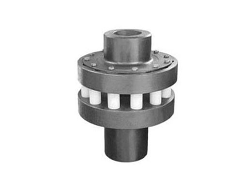
 HL type elastic pin couplingThe elastic pin coupling uses a number of non...
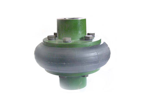 UL tire couplingUL tire coupling is a highly elastic coupling...
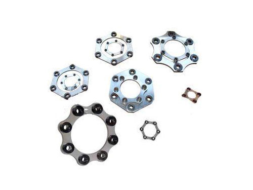 Diaphragm coupling diaphragmDiaphragm couplings have a wide range of applications...
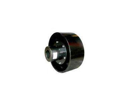 LTZ elastic sleeve pin coupling with brake wheelLTZ (formerly TLL type) with brake wheel elastic sleeve pin...
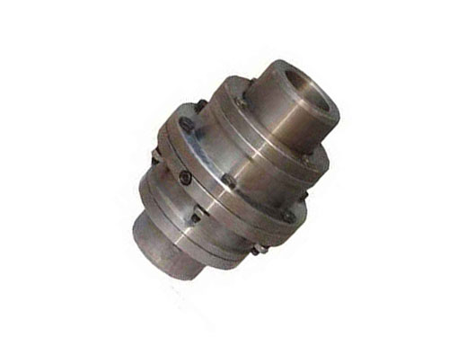 GICLZ type-drum gear couplingGⅠCLZ type—drum-shaped gear coupling drum-shaped...
The design of the stop pin of the LX elastic pin coupling and the maintenance of the diaphragm coupling
Aiming at the problems in the original standard design, the author improved the design of the retaining pin structure of the LX elastic pin coupling.described as follows:
[1] Process the inner side of the right half coupling into a "fancy" stop pin structure.That is, a groove is machined inside the flange.The groove is located at the position of the circumference of the flange hole, with a width of 4 mm × a depth of 8 mm.
[2] The flange hole of the left half coupling is designed as a reducing through hole, so that the original design of the left baffle is omitted.When replacing the shaft pin, the old shaft pin can be ejected from left to right through the small hole.
When replacing a new shaft pin, use 12#~14# iron wire around a circle in the groove and then fasten it firmly, which acts as a stop pin and replaces the original baffle.
In the field, the existing LX-type elastic pin coupling can also be modified.That is to say, it is sufficient to weld on the original coupling with a processing piece similar to the "fancy" stop pin structure on the inner side of the flange, and it will not be repeated here.
Coupling is a component that connects two shafts axially and transmits torque and motion, and has the ability to compensate for the offset of the two shafts.On this basis, the coupling should be concentric.From a mechanical point of view, the coupling is stressed. The motor drives the coupling to rotate after powering up, and then the coupling drives the device to rotate. For couplings, concentricity is very important, otherwise It will affect the motor, etc.In the mechanical transmission, the coupling is to reduce the vibration of the mechanical transmission system and reduce the impact peak load. It should also have cushioning and shock absorption performance, and sometimes also have the function of overload protection, and the coupling is concentric, the motor power consumption is normal. The speed will be very high; if the power loss increases when the coupling is not centered, it will cause the transmission rate to decrease, and the current of the motor will naturally increase, which will eventually lead to the consequence that the motor may be burned.
Maintenance of diaphragm coupling:
[1] The high circumferential speed of the diaphragm coupling is about 30m/s. It is lubricated with No. 2 grease. The open area of the middle sliding block is filled with grease. The grease change cycle is 1000 hours. Ball bearing grease is suitable for use.The high peripheral speed is about 30m/s, and it is lubricated with N220 gear oil. The open area of the middle sliding block is filled with oil. The oil change cycle is 1000 hours. Sometimes a felt pad filled with oil is used.
[2] The high circumferential speed of the diaphragm coupling is about 150m/s. It is lubricated with N150 and N220 gear oils. It requires sufficient flow to pass through the coupling continuously in the axial direction without sealing.
[3] The high peripheral speed of the diaphragm coupling is about 30m/s. It is lubricated with No. 1 grease. The amount is to fill the coupling. The grease change cycle is 1000 hours, and the sealing requirements are not strict.
Operating environment of diaphragm elastic coupling:
[1] Adapt to high temperature (-80+300) and work in harsh environments, and can operate stably under shock and vibration conditions.
[2] The ability to compensate for the misalignment of the two axes is good. Compared with the gear coupling, the angular displacement can be doubled, the reaction force is small during radial displacement, and the flexibility is large. Corresponding axial, radial and angular displacement are allowed. To displacement.
【3】Simple structure, light weight, small size, convenient assembly and disassembly.It can be assembled and disassembled without moving the machine (refer to the type with intermediate shaft), and no lubrication is required.
[4] It can accurately transmit the speed without slip, and can be used for the transmission of precision machinery.
[5] It has obvious shock absorption, no noise and no wear.
[6] The transmission rate is good, especially suitable for medium and high power transmission.
Before starting the equipment, check whether the coupling nut is loose or falling off. If so, tighten the nut with a wrench in time.The load line valve should be opened after starting the equipment with no load for 1 minute; the shutdown sequence is reversed.Insert the bolt from the outside of the small hole in the flange, and pass it through the outside of the large hole in the other flange. Put on the buffer sleeve, elastic washer, and twist the nut. Use a wrench to tighten the nut.If the installation is not suitable or the replacement is removed, the shaft and the half coupling will not be damaged.After installation, it is better to rotate freely.