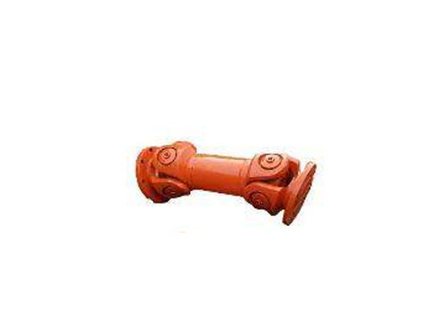
 Small size universal couplingCommon types of universal couplings are: universal...
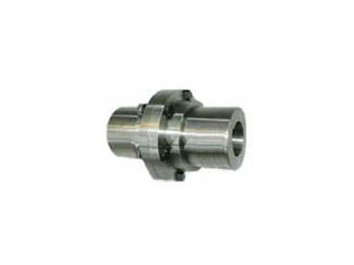 YLD type flange couplingYL type flange coupling can be made of gray cast iron or carbon...
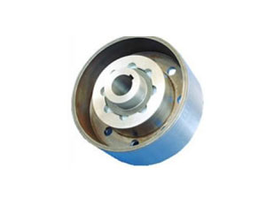 ZLL type elastic pin gear coupling with brake wheelZLL type elastic pin gear coupling with brake wheel...
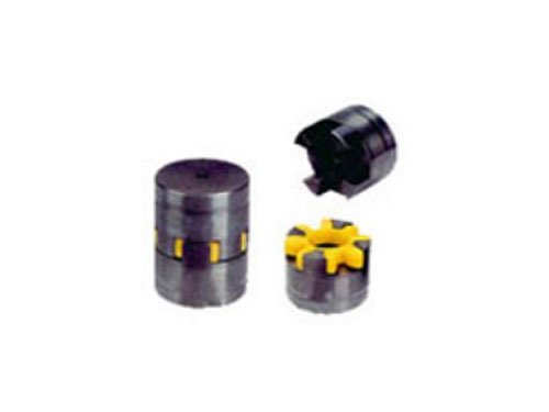 LXD type single flange star elastic couplingLXD type single flange star elastic coupling is...
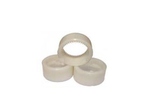 Nylon sleeve inner gear ringThe main purpose of the nylon sleeve inner gear ring is:...
Summary of common problems in the use of drum gear couplings
The tooth tip of the outer gear sleeve of the drum gear coupling is processed into an arc, that is, the tooth blank is processed into a spherical surface. In the section of the tooth center plane and tangent to the pitch cylinder surface, the teeth form a drum shape. The so-called drum type coupling Shaft.The axial gear blank of the external gear sleeve of the spur gear coupling can be machined into two kinds of linear and circular arc shapes, and the index circle and the tooth root circle are both straight lines. The meshing form of this coupling is gradually The meshing of the internal and external teeth of the open cylindrical gear is the same.The relative displacement between the two shafts is compensated by increasing the side clearance of the internal and external teeth, but the compensation amount is limited.Gear couplings have small radial dimensions, large load-bearing capacity, and are long used for shaft transmission under low-speed and heavy-duty conditions. The dynamically balanced gear coupling can be used for high-speed transmission, such as gas turbine shaft transmission .Since the angular compensation of drum gear couplings is greater than that of straight gear couplings, drum gear couplings are commonly used. Straight gear couplings are an obsolete product and should not be used as much as possible.
XNUMX. The principle of the structural characteristics of the drum gear coupling
1. High load-carrying capacity, calculated by bending strength, under the same conditions, the torque transmitted by a spur gear coupling is increased by 15-30%;
2. Reasonable structure and performance. Because the tooth side is drum-shaped, the contact of the axis is improved under the corresponding angle condition, thereby reducing the contact stress, and the load concentration at the tooth end of the spur coupling, that is, the edge Extrusion improves work performance.
3. Good compensation performance. The tooth profile of the external gear sleeve is drum-shaped, which increases the allowable relative deviation of the two connected shafts. The maximum allowable inclination angle is up to 6 degrees, and 1.5°~2.5° is generally recommended.
XNUMX. Summary of common problems in the use of drum gear couplings
(1) Oil leakage: Oil leakage is caused by poor sealing performance. When the coupling is overloaded, the oil temperature and pressure increase sharply, the rubber sealing ring is aging, the sealing performance deteriorates, and the oil leakage reduces the transmission torque, causing difficulty in starting. .
(2) Burning the motor: (1) After the coupling is adopted, the burning of the motor will still occur, mainly due to the lack of understanding of the performance of the equipment and improper use; the operating conditions of the motor are under the condition of i=0 When running, empty the oil in the coupling to prevent the motor from being burnt due to long-term overload; (2) Due to the excessively long power supply line and other reasons, when the voltage drop of the power grid is too large, the characteristic curve of the motor will change, and the motor will be Long-term operation under low voltage will increase the rated current and cause the motor to overheat and burn.
(3) Broken shaft: (1) The power output shaft of the coupling is cantilevered and adopts radial thrust bearings.When installing this kind of support structure, the bearing clearance and bevel gear clearance should be adjusted to ensure the correct meshing.After the bearing is worn, adjust and replace it in time.Otherwise, once the gap becomes larger, the normal meshing of the bevel gear will be destroyed, causing additional load, resulting in deterioration of bearing conditions, gear teeth, crimped shafts, or even breakage; (2) The coupling is only subjected to static balance tests when leaving the factory. During high-speed operation, the additional load and shaft vibration caused by imbalance will deteriorate the working state of the shaft; (3) The bevel gear shaft of the conveyor reducer is installed together with the coupling, and the structure is unreasonable , The weight is large, and it is easy to collide during installation and handling to cause bending and deformation of the shaft; (4) When the coupling is started, the force and stress condition of the shaft deteriorates, resulting in the deformation of the spline.
Due to various reasons, the center of mass or inertial principal axis of the drum gear coupling does not coincide with the axis of rotation, and the phenomenon of unbalanced centrifugal inertial force, centrifugal inertial couple force and dynamic deflection (vibration shape) will occur during operation, which is called The unbalance phenomenon of the rotor, this unbalance phenomenon will inevitably cause the vibration of the shaft system, thereby affecting the normal operation and service life of the machine, so it is important to pay attention to it.The degree of unbalance (unbalance U) is usually expressed by the product mr of the mass m of the rotor and the distance r from the center of mass to the axis of rotation of the rotor, which is called the product of mass diameter.It is also expressed by the product of mass diameter per unit mass, called the eccentricity e (not geometrically eccentric.) The product of mass diameter mr is a relative quantity related to the mass of the rotor, while the eccentricity e is a value that has nothing to do with the mass of the rotor.的量。 The amount.The former is relatively intuitive and is often used for the balancing operation of a specific given rotor, while the latter is used to measure the pros and cons of the rotor balance or to check the balance accuracy. The balance grade standard of the coupling is evaluated by e.For a flexible rotor, use the mode eccentricity (the nth mode) en=Un/mn, and Un and mn are the nth mode and the first mode quality respectively.