 JMJ diaphragm couplingJMJ diaphragm coupling torque control range...
 FZ type double fulcrum square bottom plate rackFZ type double fulcrum square bottom plate rack series is suitable for...
 FCL type elastic sleeve pin couplingThe characteristics of FCL type elastic sleeve pin coupling...
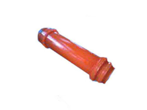 WGT type gear coupling with intermediate sleeveWGT type connecting middle sleeve gear coupling is working...
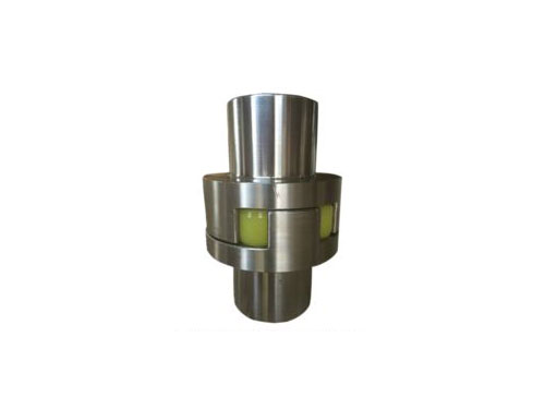 ML plum-shaped elastic couplingML plum-shaped elastic coupling and other coupling...
The lubrication method of drum gear coupling and the work of diaphragm coupling
After the drum-shaped gear coupling is installed, the work intensity is high, and due to long-term operation, it will wear out the internal and external teeth, so regular maintenance and maintenance are required.Lubrication method of drum gear coupling:
1. Gravity lubrication.The lubricating oil is injected from the nozzle and flows through the gear backlash, and flows out from the small hole of the sleeve. This lubrication method mainly plays a cooling role, and it is difficult to form an oil film. The tooth surface wears faster than the following lubrication.
2. Lubrication.The lubricating oil is sprayed into the small holes at the bottom of the gear teeth, and the oil enters the meshing surface under the action of centrifugal force to play the role of lubrication and cooling.The oil flows out from both sides of the tooth after passing through the meshing surface.With this type of lubrication, the oil circulates continuously, and the magazine flows out, and the pressure caused by the injected lubricating oil enters the gear tooth meshing surface under the action of centrifugal force, so it has a good lubrication and cooling operation and is suitable for heavy-duty occasions.
3. Oil storage lubrication.The lubricating oil is injected from the nozzle, and the lubricating oil layer is maintained on the outer circle of the gear due to the centrifugal force of the lubricating oil during rotation.This lubrication method will leave the magazine in the ring gear, and the oil flow will have a poor heat dissipation effect, so it is only suitable for occasions with low power and low speed.There is also a non-flowing oil storage lubrication method belonging to this type, which is to pour grease into the interior and then seal it.
The drum-shaped gear coupling is developed and evolved from the ordinary spur gear coupling. The main difference is that the tooth surface of the outer gear sleeve is drum-shaped.Ordinary drum gear couplings are composed of 1 or 2 pairs of internal and external gear meshing components. For a single pair of internal and external gear meshing components, due to installation errors, adjustment of the working axis, deformation of the load frame, and subsidence of the foundation, etc. Due to the influence of factors, the angular displacement of the two axes will reduce the force meshing tooth pair.The greater the angular displacement, the fewer the force meshing tooth pairs, the greater the contact stress of the tooth pairs, and the greater the tooth root bending stress.Therefore, the angular displacement has a direct relationship with the load-bearing size of the inner and outer teeth, which is one of the important parameters of the drum gear coupling.
From the perspective of working movement, due to the angular displacement of the inner and outer teeth, the relative movement of the tooth pair occurs. When the drum-shaped gear coupling rotates, if the inner tooth axis is used as the reference, the drum-shaped outer tooth has two movements relative to the inner tooth. One is the swing of the teeth, and the other is the flip of the teeth.Therefore, for the life of the drum-shaped external tooth, one is the extrusion of the tooth surface, and the important aspect is the wear of the tooth surface due to the swing of the tooth.
The drum gear coupling has the following advantages: First, the angular displacement of the inner and outer tooth axis is large, generally 1°~1°30' is recommended.In special use cases, the inclination angle of the drum gear coupling can reach 6°.Second, from the point of view of bending strength, the transmission torque of the drum gear type is 15%-20% higher than that of the spur gear coupling under the same working conditions.The third is because the drum tooth flanks are in a drum shape, and the axis is inclined at an angle. The drum tooth flanks and the internal tooth flanks are contacted and stressed. The contact conditions and contact stress are reduced, which changes the outer surface of the ordinary spur gear coupling. The ends of the teeth are loaded, and the edges are squeezed.Fourth, because the outer tooth surface is a drum-shaped surface, the gap between the inner and outer teeth is reduced, the impact of the inner and outer teeth is small during operation, and the service life is prolonged.Fifth, in terms of manufacturing, the processability of processing drum-shaped external teeth is almost the same as that of ordinary straight teeth, so the economy is good.
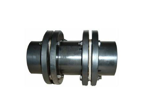
The diaphragm coupling relies on bolts and diaphragms to transmit torque. The bolt holes under the diaphragm set are equipped with crown bushes and crown washers. The bushes and bolts with pins are matched with a small clearance fit, and the concentricity and mating surface requirements are high. The concentricity between the half coupling and the intermediate shaft is positioned by the bushing and the bolt with pin. If the installation direction is opposite, the thickness of the washer is added, resulting in a shorter positioning surface, poor concentricity, and distortion of the diaphragm assembly.In a rotating unit, the distortion of the diaphragm results in poor concentricity, which seriously affects the stability of the unit's shaft vibration. This is also one of the reasons for the vibration of the unit at a speed of 9000r/min during the test run, which is higher than this speed.
According to the length of the bolt with pin, adopt the installation method between positive and negative phases. The adjusting washer and the fastening nut are installed on the same side, and the positioning is accurate.The bolt installation direction before the rectification is shown in Figure 8. The bolt installation direction after the rectification, the positioning length of the bolt with pin is large, and the optional installation has good positioning and concentricity.
When the diaphragm coupling is working, it will be subject to the overlap stress caused by the torque, the bending stress caused by the deflection of the axis, the centrifugal stress caused by the rotation of the bolt and the diaphragm, and the radial and angular deviation of the diaphragm. Bending stress, etc.The superimposed stress will cause the bolt to produce shear stress; the bending stress will cause the bolt to produce tensile or compressive stress, and the stress will alternate once per rotation of the shaft; the centrifugal force will cause the bolt to produce shear stress, which changes with the speed.Combined with the failure mode of the front pump diaphragm coupling in Jurong Power Plant, it can be seen that the diaphragm near the bolt hole is subjected to the cyclic action of alternating stress and compound stress, and fatigue fracture occurs.
The instability of the diaphragm under pressure is a common failure of the diaphragm. From the mechanics of materials, if the stress of the compressed diaphragm is greater than the critical stress when the diaphragm is subjected to a large torque, the diaphragm will lose its original linear shape balance and change It is slightly bent.
Diaphragm fracture under tension is a relatively common fault. It was found that the dangerous section near the bolt hole of the coupling diaphragm was easily broken.The force analysis of the tensioned diaphragm found that: when the four sides are tensioned and the load distribution is uniform, the diaphragm will not break and fail; if the load distribution is uneven, it may be in the process of retracting the diaphragm. There was a phenomenon that several diaphragms were pulled off.Working under long-term misalignment, if the deviation exceeds the compensation range of the coupling, the diaphragm coupling will experience peak torque, of which 4 groups of compressed diaphragm groups are unstable, and the other 4 groups of tensioned diaphragms Will bear all the torque and the tensile force will be doubled.If the diaphragm is in a non-uniform stress state for a long time, the stress on the inner side of the bolt holes at both ends of the diaphragm will exceed the curved clothes of the material, causing it to be broken and damaged. As the number of load-bearing diaphragms is gradually reduced and the stress is uneven, the original stress The diaphragm with lower stress will also be broken, and then the entire group of diaphragms will be broken.
Next:Nothing